Toyota CH-R Service Manual: Removal
REMOVAL
CAUTION / NOTICE / HINT
The necessary procedures (adjustment, calibration, initialization, or registration) that must be performed after parts are removed, installed, or replaced during the spiral cable sub-assembly removal/installation are shown below.
Necessary Procedure After Parts Removed/Installed/Replaced|
Replacement Part or Procedure |
Necessary Procedures |
Effects / Inoperative when not performed |
Link |
|---|---|---|---|
|
Disconnect cable from negative battery terminal |
Initialize back door lock |
Power door lock control system |
|
|
Memorize steering angle neutral point |
Lane departure alert system (w/ Steering Control) |
|
|
|
Pre-collision system |
PROCEDURE
1. REMOVE STEERING WHEEL ASSEMBLY
Click here .gif)
2. ALIGN FRONT WHEELS FACING STRAIGHT AHEAD
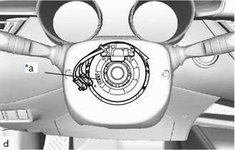
3. INSPECT SPIRAL CABLE WITH SENSOR SUB-ASSEMBLY (w/o Steering Heater)
|
(a) Check the flat cable shown in the illustration. If the flat cable shown in the illustration is not visible, it is possible that the spiral cable with sensor sub-assembly is broken. Replace the spiral cable with sensor sub-assembly with a new one. |
|
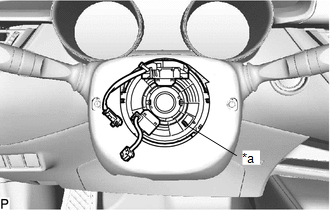
4. INSPECT SPIRAL CABLE WITH SENSOR SUB-ASSEMBLY (w/ Steering Heater)
|
(a) Check the flat cable shown in the illustration. If the flat cable shown in the illustration is not visible, it is possible that the spiral cable with sensor sub-assembly is broken. Replace the spiral cable with sensor sub-assembly with a new one. |
|
5. REMOVE LOWER STEERING COLUMN COVER SUB-ASSEMBLY
Click here
6. REMOVE UPPER STEERING COLUMN COVER
Click here
7. REMOVE SPIRAL CABLE WITH SENSOR SUB-ASSEMBLY
NOTICE:
- Do not replace the spiral cable with sensor sub-assembly with the battery connected and the ignition switch ON.
- Do not rotate the spiral cable with sensor sub-assembly without the steering wheel assembly installed, with the battery connected and the ignition switch ON.
- Ensure that the steering wheel assembly is installed and aligned straight when inspecting the steering sensor.
(a) Check that the ignition switch off.
(b) Check that the cable is disconnected from the negative (-) battery terminal.
CAUTION:
Wait at least 90 seconds after disconnecting the cable from the negative (-) battery terminal to disable the SRS system.
.png)
(c) Check that the front wheels are aligned facing straight ahead.
|
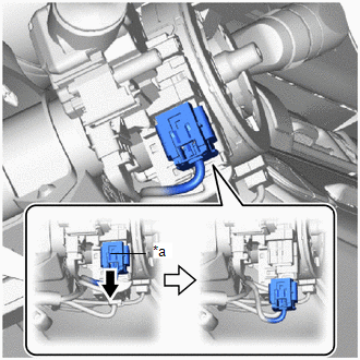
(d) Slide the slider to release the lock, and then disconnect the yellow airbag connector from the spiral cable with sensor sub-assembly. NOTICE: When disconnecting any airbag connector, take care not to damage the airbag wire harness. |
|
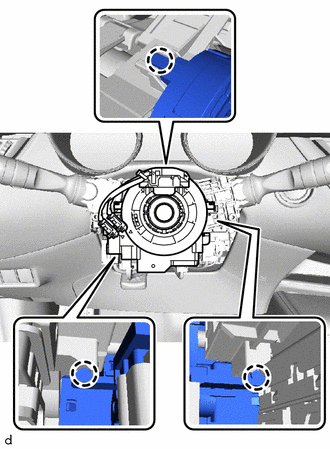
(e) Disconnect each connector from the spiral cable with sensor sub-assembly.
|
(f) Disengage the claws to remove the spiral cable with sensor sub-assembly. NOTICE:
|
|
 Inspection
INSPECTION
PROCEDURE
1. INSPECT SPIRAL CABLE SUB-ASSEMBLY
NOTICE:
Do not remove the steering sensor from the spiral cable sub-assembly
when inspecting the spiral cable sub-assembly.
...
 Installation
INSTALLATION
PROCEDURE
1. INSPECT SPIRAL CABLE SUB-ASSEMBLY (w/o Steering Heater)
NOTICE:
If the steering sensor is installed to a misaligned spiral cable sub-assembly,
DTCs for an abnormal stee ...
Other materials:
Toyota CH-R Service Manual > Rear Door Belt Moulding: Removal
REMOVAL
CAUTION / NOTICE / HINT
The necessary procedures (adjustment, calibration, initialization, or registration)
that must be performed after parts are removed and installed, or replaced during
the rear door belt moulding removal/installation are shown below.
Necessary Procedure After Part ...
Toyota CH-R Service Manual > Lighting (int): Room Light
Components
COMPONENTS
ILLUSTRATION
*1
NO. 1 ROOM LIGHT ASSEMBLY
*2
NO. 2 ROOM LIGHT BULB
*3
ROOM LIGHT LENS
*4
ROOM LIGHT HOUSING
Removal
REMOVAL
PROCEDURE
1. REMOVE NO. 1 ROOM LIGHT A ...
Toyota C-HR (AX20) 2023-2026 Owner's Manual
Toyota CH-R Owners Manual
- For safety and security
- Instrument cluster
- Operation of each component
- Driving
- Interior features
- Maintenance and care
- When trouble arises
- Vehicle specifications
- For owners
Toyota CH-R Service Manual
- Introduction
- Maintenance
- Audio / Video
- Cellular Communication
- Navigation / Multi Info Display
- Park Assist / Monitoring
- Brake (front)
- Brake (rear)
- Brake Control / Dynamic Control Systems
- Brake System (other)
- Parking Brake
- Axle And Differential
- Drive Shaft / Propeller Shaft
- K114 Cvt
- 3zr-fae Battery / Charging
- Networking
- Power Distribution
- Power Assist Systems
- Steering Column
- Steering Gear / Linkage
- Alignment / Handling Diagnosis
- Front Suspension
- Rear Suspension
- Tire / Wheel
- Tire Pressure Monitoring
- Door / Hatch
- Exterior Panels / Trim
- Horn
- Lighting (ext)
- Mirror (ext)
- Window / Glass
- Wiper / Washer
- Door Lock
- Heating / Air Conditioning
- Interior Panels / Trim
- Lighting (int)
- Meter / Gauge / Display
- Mirror (int)
- Power Outlets (int)
- Pre-collision
- Seat
- Seat Belt
- Supplemental Restraint Systems
- Theft Deterrent / Keyless Entry

0.0086