Toyota CH-R Service Manual: Installation
INSTALLATION
PROCEDURE
1. INSPECT SPIRAL CABLE SUB-ASSEMBLY (w/o Steering Heater)
NOTICE:
If the steering sensor is installed to a misaligned spiral cable sub-assembly, DTCs for an abnormal steering sensor value such as DTC B1801, C1231 and C1433 will be stored and it will be impossible to correct the problem. If this happens, replace the spiral cable with sensor sub-assembly with a new one.
|
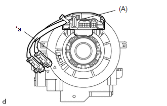
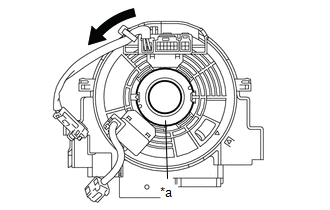
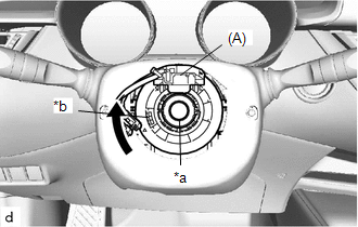
(a) Check if the spiral cable sub-assembly is centered. HINT: When the spiral cable sub-assembly is centered, the part (A) is positioned at the top and the flat cable shown in the illustration is visible. |
|
(b) If the spiral cable sub-assembly is not centered, center it.
|
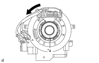
(1) While pushing on the interlock shown in the illustration, rotate the spiral cable sub-assembly counterclockwise slowly by hand until it stops. NOTICE:
|
|
|
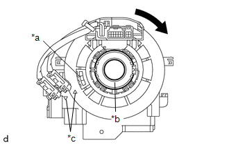
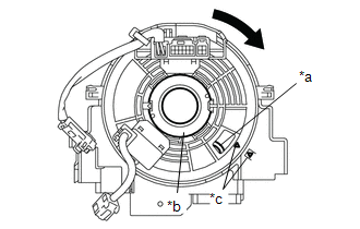
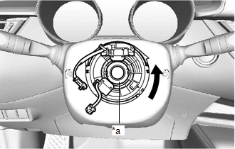
(2) While pushing on the interlock shown in the illustration, rotate the spiral cable sub-assembly clockwise approximately 2.5 times to the position where the alignment marks are aligned and the flat cable shown in the illustration is visible. HINT: The spiral cable sub-assembly can be rotated approximately 2.5 turns to both the left and right from the center. |
|
2. INSPECT SPIRAL CABLE SUB-ASSEMBLY (w/ Steering Heater)
NOTICE:
If the steering sensor is installed to a misaligned spiral cable sub-assembly, DTCs for an abnormal steering sensor value such as DTC B1801, C1231 and C1433 will be stored and it will be impossible to correct the problem. If this happens, replace the spiral cable with sensor sub-assembly with a new one.
|
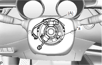
(a) Check if the spiral cable sub-assembly is centered. HINT: When the spiral cable sub-assembly is centered, the part (A) is positioned at the top and the flat cable shown in the illustration is visible. |
|
(b) If the spiral cable sub-assembly is not centered, center it.
|
(1) While pushing on the interlock shown in the illustration, rotate the spiral cable sub-assembly counterclockwise slowly by hand until it stops. NOTICE:
|
|
|
(2) While pushing on the interlock shown in the illustration, rotate the spiral cable sub-assembly clockwise approximately 2.5 times to the position where the alignment marks are aligned and the flat cable shown in the illustration is visible. HINT: The spiral cable sub-assembly can be rotated approximately 2.5 turns to both the left and right from the center. |
|
3. INSTALL SPIRAL CABLE WITH SENSOR SUB-ASSEMBLY
NOTICE:
- Do not replace the spiral cable with sensor sub-assembly with the battery connected and the ignition switch ON.
- Do not rotate the spiral cable with sensor sub-assembly without the steering wheel assembly installed, with the battery connected and the ignition switch ON.
- Ensure that the steering wheel assembly is installed and aligned straight when inspecting the steering sensor.
(a) Check that the ignition switch off.
(b) Check that the cable is disconnected from the negative (-) battery terminal.
CAUTION:
Wait at least 90 seconds after disconnecting the cable from the negative (-) battery terminal to disable the SRS system.
.png)
(c) Check that the front wheels are aligned facing straight ahead.
|
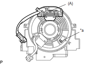
(d) Engage the claws to install the spiral cable with sensor sub-assembly. |
|
.png)
(e) Connect each connector.
4. INSTALL UPPER STEERING COLUMN COVER
Click here .gif)
5. INSTALL LOWER STEERING COLUMN COVER SUB-ASSEMBLY
Click here
6. ALIGN FRONT WHEELS FACING STRAIGHT AHEAD
7. INSPECT AND ADJUST SPIRAL CABLE WITH SENSOR SUB-ASSEMBLY (w/o Steering Heater)
NOTICE:
Do not adjust the spiral cable with sensor sub-assembly with the battery connected and the ignition switch ON.
(a) Check that the ignition switch off.
(b) Check that the cable is disconnected from the negative (-) battery terminal.
CAUTION:
Wait at least 90 seconds after disconnecting the cable from the negative (-) battery terminal to disable the SRS system.
|
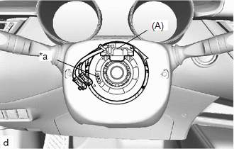
(c) Check if the spiral cable with sensor sub-assembly is centered. HINT: When the spiral cable with sensor sub-assembly is centered, the part (A) is positioned at the top and the flat cable shown in the illustration is visible. |
|
(d) If the spiral cable with sensor sub-assembly is not centered, center it.
|
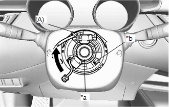
(1) While pushing on the interlock shown in the illustration, rotate the spiral cable with sensor sub-assembly counterclockwise slowly by hand until it stops. NOTICE:
|
|
|
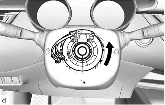
(2) While pushing on the interlock shown in the illustration, rotate the spiral cable with sensor sub-assembly clockwise approximately 2.5 times to the position where the part (A) is positioned at the top and the flat cable shown in the illustration is visible. HINT: The spiral cable with sensor sub-assembly can be rotated approximately 2.5 times to both the left and right from the center. |
|
8. INSPECT AND ADJUST SPIRAL CABLE WITH SENSOR SUB-ASSEMBLY (w/ Steering Heater)
NOTICE:
Do not adjust the spiral cable with sensor sub-assembly with the battery connected and the ignition switch ON.
(a) Check that the ignition switch off.
(b) Check that the cable is disconnected from the negative (-) battery terminal.
CAUTION:
Wait at least 90 seconds after disconnecting the cable from the negative (-) battery terminal to disable the SRS system.
|
(c) Check if the spiral cable with sensor sub-assembly is centered. HINT: When the spiral cable with sensor sub-assembly is centered, the part (A) is positioned at the top and the flat cable shown in the illustration is visible. |
|
(d) If the spiral cable with sensor sub-assembly is not centered, center it.
|
(1) While pushing on the interlock shown in the illustration, rotate the spiral cable with sensor sub-assembly counterclockwise slowly by hand until it stops. NOTICE:
|
|
|
(2) While pushing on the interlock shown in the illustration, rotate the spiral cable with sensor sub-assembly clockwise approximately 2.5 times to the position where the part (A) is positioned at the top and the flat cable shown in the illustration is visible. HINT: The spiral cable with sensor sub-assembly can be rotated approximately 2.5 times to both the left and right from the center. |
|
9. INSTALL STEERING WHEEL ASSEMBLY
Click here
 Removal
REMOVAL
CAUTION / NOTICE / HINT
The necessary procedures (adjustment, calibration, initialization, or registration)
that must be performed after parts are removed, installed, or replaced during th ...

Other materials:
Toyota CH-R Service Manual > Safety Connect System: Green Indicator Remains Off
DESCRIPTION
After turning the ignition switch ON, the DCM (Telematics Transceiver) will enter
into self check mode. The manual (SOS) switch red indicator will illuminate for
2 seconds and turn off followed by the manual (SOS) switch green indicator illuminating
and remaining on under normal o ...
Toyota CH-R Service Manual > Continuously Variable Transaxle System: Pressure Control Solenoid "K" Electrical (P282B)
DESCRIPTION
According to current control by the ECM, the shift solenoid valve SLS controls
secondary pulley pressure and belt clamping pressure in accordance with the input
shaft torque.
*1
Spool Valve
*2
Sleeve
*3
Solen ...
Toyota C-HR (AX20) 2023-2026 Owner's Manual
Toyota CH-R Owners Manual
- For safety and security
- Instrument cluster
- Operation of each component
- Driving
- Interior features
- Maintenance and care
- When trouble arises
- Vehicle specifications
- For owners
Toyota CH-R Service Manual
- Introduction
- Maintenance
- Audio / Video
- Cellular Communication
- Navigation / Multi Info Display
- Park Assist / Monitoring
- Brake (front)
- Brake (rear)
- Brake Control / Dynamic Control Systems
- Brake System (other)
- Parking Brake
- Axle And Differential
- Drive Shaft / Propeller Shaft
- K114 Cvt
- 3zr-fae Battery / Charging
- Networking
- Power Distribution
- Power Assist Systems
- Steering Column
- Steering Gear / Linkage
- Alignment / Handling Diagnosis
- Front Suspension
- Rear Suspension
- Tire / Wheel
- Tire Pressure Monitoring
- Door / Hatch
- Exterior Panels / Trim
- Horn
- Lighting (ext)
- Mirror (ext)
- Window / Glass
- Wiper / Washer
- Door Lock
- Heating / Air Conditioning
- Interior Panels / Trim
- Lighting (int)
- Meter / Gauge / Display
- Mirror (int)
- Power Outlets (int)
- Pre-collision
- Seat
- Seat Belt
- Supplemental Restraint Systems
- Theft Deterrent / Keyless Entry

0.0094