Toyota CH-R Service Manual: Terminals Of Ecu
TERMINALS OF ECU
REAR TELEVISION CAMERA ASSEMBLY
(a) Disconnect the S11 rear television camera assembly connector.

(b) Measure the voltage of each terminal of the wire harness side connector.
|
Terminal No. (Symbol) |
Wiring Color |
Terminal Description |
Condition |
Specified Condition |
|---|---|---|---|---|
|
S11-6 (CB+) - Body ground |
G - Body ground |
Power source |
Ignition switch ACC |
5.5 to 7.05 V |
If the result is not as specified, there may be a malfunction on the wire harness side.
(c) Reconnect the S11 rear television camera assembly connector.
(d) Measure the resistance and check for pulses at each terminal of the connector.
|
Terminal No. (Symbol) |
Wiring Color |
Terminal Description |
Condition |
Specified Condition |
|---|---|---|---|---|
|
S11-3 (CV+) - S11-2 (CV-) |
W - R |
Video signal |
Ignition switch ON Shift lever in R Camera lens not covered, displaying an image |
Pulse generation (Refer to waveform 1) |
|
Ignition switch ON Shift lever in R Camera lens covered, blacking out the screen |
Pulse generation (Refer to waveform 2) |
|||
|
S11-5 (CGND) - Body ground |
B - Body ground |
Camera ground |
Always |
Below 1 Ω |
HINT:
A waterproof connector is used for the rear television camera assembly. Therefore, inspect the waveform at the radio and display receiver assembly with the connector connected.
If the result is not as specified, the rear television camera assembly may be malfunctioning.
(e) Reference (Oscilloscope waveform):
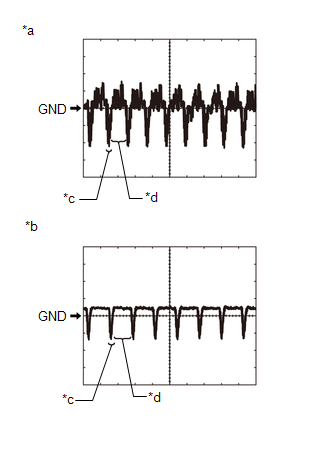
|
*a |
Waveform 1 (camera lens is not covered, displaying an image) |
|
*b |
Waveform 2 (camera lens is covered, blacking out the screen) |
|
*c |
Synchronization Signal |
|
*d |
Video Waveform |
HINT:
A waterproof connector is used for the rear television camera assembly. Therefore, inspect the waveform at the radio and display receiver assembly with the connector connected.
(1) Waveform 1 (camera lens is not covered, displaying an image)
|
Item |
Content |
|---|---|
|
Measurement terminal |
S11-3 (CV+) - S11-2 (CV-) |
|
Measurement setting |
200 mV/DIV., 50 μs./DIV. |
|
Condition |
Ignition switch ON, shift lever in R |
HINT:
- The video waveform changes according to the image sent by the rear television camera assembly.
- The video waveform is constantly output when the ignition switch is turned to ACC.
(2) Waveform 2 (camera lens is covered, blacking out the screen)
|
Item |
Content |
|---|---|
|
Measurement terminal |
S11-3 (CV+) - S11-2 (CV-) |
|
Measurement setting |
200 mV/DIV., 50 μs./DIV. |
|
Condition |
Ignition switch ON, shift lever in R |
HINT:
- The video waveform changes according to the image sent by the rear television camera assembly.
- The video waveform is constantly output when the ignition switch is turned to ACC.
RADIO AND DISPLAY RECEIVER ASSEMBLY
HINT:
Check from the rear of the connector while it is connected to the components.
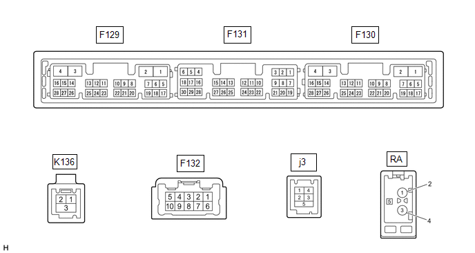
|
Terminal No. (Symbol) |
Wiring Color |
Terminal Description |
Condition |
Specified Condition |
|---|---|---|---|---|
|
F131-26 (CSLD) - Body ground |
Shield - Body ground |
Shield ground |
Always |
Below 1 V |
|
F131-27 (CGND) - Body ground |
B - Body ground |
Camera ground |
Always |
Below 1 V |
|
F131-28 (V+) - F129-1 (GND1) |
R - LA*1 W - LA*2 |
Video signal |
Ignition switch ON Shift lever in R Camera lens not covered, displaying an image |
Pulse generation (Refer to waveform 1) |
|
Ignition switch ON Shift lever in R Camera lens covered, blacking out screen |
Pulse generation (Refer to waveform 2) |
|||
|
F131-29 (V-) - F129-1 (GND1) |
W - LA*1 R - LA*2 |
Ground |
Always |
Below 1 V |
|
F131-30 (CA+) - F129-1 (GND1) |
G - LA |
Rear television camera assembly power supply |
Ignition switch ACC |
5.5 to 7.05 V |
- *1: for TMC Made
- *2: for TMMT Made
(a) Reference (Oscilloscope waveform):
(1) Waveform 1 (camera lens not covered, displaying an image)
|
Item |
Content |
|---|---|
|
Measurement terminal |
F131-28 (V+) - F129-1 (GND1) |
|
Measurement setting |
200 mV/DIV., 50 μs/DIV. |
|
Condition |
Ignition switch ON, shift lever in R |
HINT:
- The video waveform changes according to the image sent by the rear television camera assembly.
- The video waveform is constantly output when the ignition switch is turned to ACC.
|
*a |
Waveform 1 (camera lens not covered, displaying an image) |
|
*b |
Waveform 2 (camera lens covered, blacking out the screen) |
|
*c |
Synchronization Signal |
|
*d |
Video Waveform |
(2) Waveform 2 (camera lens covered, blacking out the screen)
|
Item |
Content |
|---|---|
|
Measurement terminal |
F131-28 (V+) - F129-1 (GND1) |
|
Measurement setting |
200 mV/DIV., 50 μs/DIV. |
|
Condition |
Ignition switch ON, shift lever in R |
HINT:
- The video waveform changes according to the image sent by the rear television camera assembly.
- The video waveform is constantly output when the ignition switch is turned to ACC.
 Problem Symptoms Table
PROBLEM SYMPTOMS TABLE
HINT:
Use the table below to help determine the cause of problem symptoms.
If multiple suspected areas are listed, the potential causes of the symptoms
are lis ...
 Diagnosis System
DIAGNOSIS SYSTEM
DESCRIPTION
(a) Diagnostic Trouble Codes (DTCs) can be read from the Data Link Connector
3 (DLC3) of the vehicle. When the rear view monitor system seems to be malfunctioning,
u ...
Other materials:
Toyota CH-R Service Manual > Terms: Abbreviations Used In Manual
ABBREVIATIONS USED IN MANUAL
Abbreviation
Meaning
ABS
Anti-Lock Brake System
A/C
Air Conditioner
AC
Alternating Current
ACC
Accessory
ACIS
...
Toyota CH-R Service Manual > Steering Column Assembly: Installation
INSTALLATION
PROCEDURE
1. ALIGN FRONT WHEELS FACING STRAIGHT AHEAD
2. INSTALL STEERING COLUMN ASSEMBLY
NOTICE:
Make sure that the wire harness is not interfering with the steering column assembly.
(a) Install the steering column assembly with the bolt and 2 nuts.
Torque:
36 N·m {367 kgf·c ...
Toyota C-HR (AX20) 2023-2026 Owner's Manual
Toyota CH-R Owners Manual
- For safety and security
- Instrument cluster
- Operation of each component
- Driving
- Interior features
- Maintenance and care
- When trouble arises
- Vehicle specifications
- For owners
Toyota CH-R Service Manual
- Introduction
- Maintenance
- Audio / Video
- Cellular Communication
- Navigation / Multi Info Display
- Park Assist / Monitoring
- Brake (front)
- Brake (rear)
- Brake Control / Dynamic Control Systems
- Brake System (other)
- Parking Brake
- Axle And Differential
- Drive Shaft / Propeller Shaft
- K114 Cvt
- 3zr-fae Battery / Charging
- Networking
- Power Distribution
- Power Assist Systems
- Steering Column
- Steering Gear / Linkage
- Alignment / Handling Diagnosis
- Front Suspension
- Rear Suspension
- Tire / Wheel
- Tire Pressure Monitoring
- Door / Hatch
- Exterior Panels / Trim
- Horn
- Lighting (ext)
- Mirror (ext)
- Window / Glass
- Wiper / Washer
- Door Lock
- Heating / Air Conditioning
- Interior Panels / Trim
- Lighting (int)
- Meter / Gauge / Display
- Mirror (int)
- Power Outlets (int)
- Pre-collision
- Seat
- Seat Belt
- Supplemental Restraint Systems
- Theft Deterrent / Keyless Entry

0.0085