Toyota CH-R Service Manual: Parts Location
PARTS LOCATION
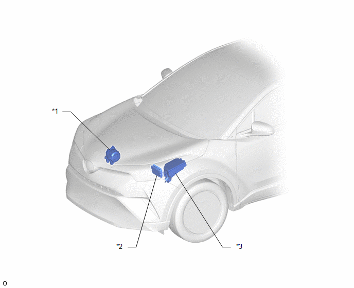
ILLUSTRATION
|
*1 |
GENERATOR ASSEMBLY |
*2 |
ECM |
|
*3 |
NO. 1 ENGINE ROOM RELAY BLOCK - ECU-B NO. 3 FUSE |
- |
- |
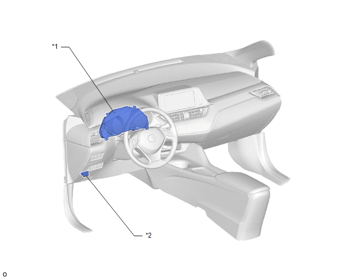
ILLUSTRATION
|
*1 |
COMBINATION METER ASSEMBLY |
*2 |
DLC3 |
 Charging System
...
 Precaution
PRECAUTION
IGNITION SWITCH EXPRESSIONS
HINT:
The type of ignition switch used on this model differs depending on the specifications
of the vehicle. The expressions listed in the table below are u ...
Other materials:
Toyota CH-R Service Manual > Occupant Classification Ecu: On-vehicle Inspection
ON-VEHICLE INSPECTION
CAUTION / NOTICE / HINT
CAUTION:
Be sure to correctly follow the removal and installation procedures for the occupant
detection ECU.
PROCEDURE
1. INSPECT OCCUPANT DETECTION ECU (for Vehicle not Involved in Collision)
(a) Perform a diagnostic system check.
Click here
...
Toyota CH-R Service Manual > Smart Key System(for Start Function): How To Proceed With Troubleshooting
CAUTION / NOTICE / HINT
HINT:
Use these procedures to troubleshoot the smart key system (for Start
Function).
*: Use the Techstream.
PROCEDURE
1.
VEHICLE BROUGHT TO WORKSHOP
NEXT
...
Toyota C-HR (AX20) 2023-2026 Owner's Manual
Toyota CH-R Owners Manual
- For safety and security
- Instrument cluster
- Operation of each component
- Driving
- Interior features
- Maintenance and care
- When trouble arises
- Vehicle specifications
- For owners
Toyota CH-R Service Manual
- Introduction
- Maintenance
- Audio / Video
- Cellular Communication
- Navigation / Multi Info Display
- Park Assist / Monitoring
- Brake (front)
- Brake (rear)
- Brake Control / Dynamic Control Systems
- Brake System (other)
- Parking Brake
- Axle And Differential
- Drive Shaft / Propeller Shaft
- K114 Cvt
- 3zr-fae Battery / Charging
- Networking
- Power Distribution
- Power Assist Systems
- Steering Column
- Steering Gear / Linkage
- Alignment / Handling Diagnosis
- Front Suspension
- Rear Suspension
- Tire / Wheel
- Tire Pressure Monitoring
- Door / Hatch
- Exterior Panels / Trim
- Horn
- Lighting (ext)
- Mirror (ext)
- Window / Glass
- Wiper / Washer
- Door Lock
- Heating / Air Conditioning
- Interior Panels / Trim
- Lighting (int)
- Meter / Gauge / Display
- Mirror (int)
- Power Outlets (int)
- Pre-collision
- Seat
- Seat Belt
- Supplemental Restraint Systems
- Theft Deterrent / Keyless Entry

0.0068