Toyota CH-R Service Manual: Adjustment
ADJUSTMENT
CAUTION / NOTICE / HINT
|
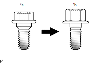
*a |
Centering Bolt |
|
*b |
Standard Bolt |
HINT:
- Use the same procedure for the RH side and LH side.
- The following procedure is for the LH side.
- Centering bolts are used to install the door hinges to the vehicle body and door. The door cannot be adjusted with the centering bolts installed. Substitute the centering bolts with standard bolts when making adjustments.
- The specified torque for standard bolts is shown in the standard bolt
chart.
Click here
.gif)
PROCEDURE
1. INSPECT FRONT DOOR PANEL SUB-ASSEMBLY
(a) Check that the clearance measurements of areas "A" to "Y" are within the standard ranges.
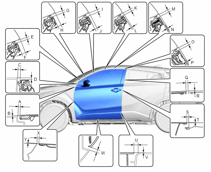 Standard Clearance
|
Area |
Measurement |
Area |
Measurement |
|---|---|---|---|
|
A |
2.1 to 6.1 mm (0.083 to 0.240 in.) |
B |
-2.0 to 2.0 mm (-0.079 to 0.079 in.) |
|
C |
3.1 to 7.1 mm (0.122 to 0.280 in.) |
D |
2.9 to 6.9 mm (0.114 to 0.272 in.) |
|
E |
3.3 to 6.7 mm (0.130 to 0.264 in.) |
F |
7.1 to 11.1 mm (0.280 to 0.437 in.) |
|
G |
3.3 to 6.7 mm (0.130 to 0.264 in.) |
H |
5.9 to 9.9 mm (0.232 to 0.390 in.) |
|
I |
3.3 to 6.7 mm (0.130 to 0.264 in.) |
J |
3.7 to 7.7 mm (0.146 to 0.303 in.) |
|
K |
3.3 to 6.7 mm (0.130 to 0.264 in.) |
L |
1.4 to 5.4 mm (0.055 to 0.213 in.) |
|
M |
3.3 to 6.7 mm (0.130 to 0.264 in.) |
N |
1.2 to 5.2 mm (0.047 to 0.205 in.) |
|
O |
3.3 to 6.7 mm (0.130 to 0.264 in.) |
P |
0.8 to 3.8 mm (0.031 to 0.150 in.) |
|
Q |
2.4 to 6.4 mm (0.094 to 0.252 in.) |
R |
-2.0 to 2.0 mm (-0.079 to 0.079 in.) |
|
S |
2.9 to 5.3 mm (0.114 to 0.209 in.) |
T |
-1.2 to 1.2 mm (-0.047 to 0.047 in.) |
|
U |
7.5 to 11.5 mm (0.295 to 0.453 in.) |
V |
-2.0 to 2.0 mm (-0.079 to 0.079 in.) |
|
W |
3.5 to 8.5 mm (0.138 to 0.335 in.) |
X |
2.7 to 5.7 mm (0.106 to 0.224 in.) |
|
Y |
-1.5 to 1.5 mm (-0.059 to 0.059 in.) |
- |
- |
2. ADJUST FRONT DOOR PANEL SUB-ASSEMBLY
|
(a) Using SST, loosen the 4 hinge bolts on the vehicle body and adjust the door position. SST: 09812-00010 |
|
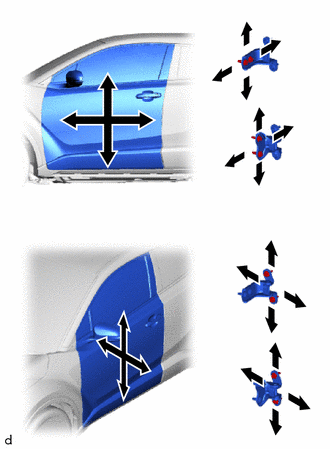
(b) Tighten the 4 hinge bolts on the vehicle body after adjustment.
Torque:
26 N·m {265 kgf·cm, 19 ft·lbf}
(c) Loosen the 4 hinge bolts on the door and adjust the door position.
(d) Tighten the 4 hinge bolts on the door after adjustment.
Torque:
for TMMT Made :
26 N·m {265 kgf·cm, 19 ft·lbf}
for TMC Made :
21 N·m {214 kgf·cm, 15 ft·lbf}
|
(e) Using a T40 "TORX" socket wrench, slightly loosen the 2 striker mounting screws. |
|
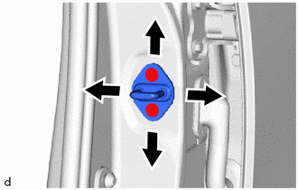
(f) Using a brass bar and a hammer, hit the striker to adjust its position.
(g) Using a T40 "TORX" socket wrench, tighten the 2 striker mounting screws after adjustment.
Torque:
23 N·m {235 kgf·cm, 17 ft·lbf}
 Disassembly
DISASSEMBLY
CAUTION / NOTICE / HINT
The necessary procedures (adjustment, calibration, initialization or registration)
that must be performed after parts are removed and installed, or replaced dur ...
 Reassembly
REASSEMBLY
CAUTION / NOTICE / HINT
HINT:
Use the same procedure for the RH side and LH side.
The following procedure is for the LH side.
PROCEDURE
1. INSTALL NO. 2 FRONT DOOR ST ...
Other materials:
Toyota CH-R Service Manual > Continuously Variable Transaxle System: Parts Location
PARTS LOCATION
ILLUSTRATION
*1
ECM
*2
SKID CONTROL ECU (BRAKE ACTUATOR ASSEMBLY)
*3
NO. 1 ENGINE ROOM RELAY BLOCK
- EFI-MAIN NO. 1 RELAY
- EFI-MAIN NO. 1 FUSE
- EFI NO. 2 FUSE
- ECU-IG2 NO. 1 FUSE
- ECU-B NO. ...
Toyota CH-R Service Manual > Meter / Gauge System: System Diagram
SYSTEM DIAGRAM
HINT:
Inspect the communication function by CAN communication system.
Click here
...
Toyota C-HR (AX20) 2023-2026 Owner's Manual
Toyota CH-R Owners Manual
- For safety and security
- Instrument cluster
- Operation of each component
- Driving
- Interior features
- Maintenance and care
- When trouble arises
- Vehicle specifications
- For owners
Toyota CH-R Service Manual
- Introduction
- Maintenance
- Audio / Video
- Cellular Communication
- Navigation / Multi Info Display
- Park Assist / Monitoring
- Brake (front)
- Brake (rear)
- Brake Control / Dynamic Control Systems
- Brake System (other)
- Parking Brake
- Axle And Differential
- Drive Shaft / Propeller Shaft
- K114 Cvt
- 3zr-fae Battery / Charging
- Networking
- Power Distribution
- Power Assist Systems
- Steering Column
- Steering Gear / Linkage
- Alignment / Handling Diagnosis
- Front Suspension
- Rear Suspension
- Tire / Wheel
- Tire Pressure Monitoring
- Door / Hatch
- Exterior Panels / Trim
- Horn
- Lighting (ext)
- Mirror (ext)
- Window / Glass
- Wiper / Washer
- Door Lock
- Heating / Air Conditioning
- Interior Panels / Trim
- Lighting (int)
- Meter / Gauge / Display
- Mirror (int)
- Power Outlets (int)
- Pre-collision
- Seat
- Seat Belt
- Supplemental Restraint Systems
- Theft Deterrent / Keyless Entry

0.0089