Toyota CH-R Service Manual: Disassembly
DISASSEMBLY
CAUTION / NOTICE / HINT
The necessary procedures (adjustment, calibration, initialization or registration) that must be performed after parts are removed and installed, or replaced during the front door removal/installation are shown below.
Necessary Procedures After Parts Removed/Installed/Replaced|
Replaced Part or Performed Procedure |
Necessary Procedure |
Effect/Inoperative when not Performed |
Link |
|---|---|---|---|
|
Disconnect cable from negative battery terminal |
Initialize back door lock |
Power door lock control system |
|
|
Memorize steering angle neutral point |
Lane departure alert system (w/ Steering Control) |
|
|
|
Pre-collision system |
|||
|
Initialize Power Window Control System |
|
|
HINT:
- Use the same procedure for the RH side and LH side.
- The following procedure is for the LH side.
PROCEDURE
1. PRECAUTION
CAUTION:
Be sure to read Precaution thoroughly before servicing.
Click here
.gif)
.png)
NOTICE:
After turning the ignition switch off, waiting time may be required before disconnecting the cable from the negative (-) battery terminal. Therefore, make sure to read the disconnecting the cable from the negative (-) battery terminal notices before proceeding with work.
Click here
2. DISCONNECT CABLE FROM NEGATIVE BATTERY TERMINAL
Click here
CAUTION:
- Wait at least 90 seconds after disconnecting the cable from the negative
(-) battery terminal to disable the SRS system.
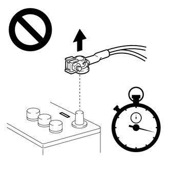
- If an SRS part is accidentally deployed, it may cause a serious injury.
NOTICE:
When disconnecting the cable, some systems need to be initialized after the cable is reconnected.
Click here
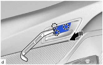
3. REMOVE FRONT DOOR INSIDE HANDLE BEZEL PLUG
(a) Using a moulding remover A, disengage the claws to remove the front door inside handle bezel plug as shown in the illustration.
.png) |
Remove in this Direction |
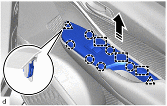
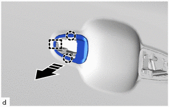
4. REMOVE MULTIPLEX NETWORK MASTER SWITCH ASSEMBLY WITH FRONT ARMREST BASE UPPER PANEL (for Driver Side)
(a) Disengage the claws, clips and guides as shown in the illustration.
|
|
Remove in this Direction |
|
(b) Disconnect the 2 connectors to remove the multiplex network master switch assembly with front armrest base upper panel. |
|
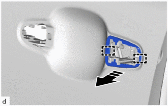
5. REMOVE POWER WINDOW REGULATOR SWITCH ASSEMBLY WITH FRONT ARMREST BASE UPPER PANEL (for Front Passenger Side)
(a) Disengage the claws, clips and guides as shown in the illustration.
|
|
Remove in this Direction |
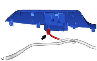
(b) w/o Rear Seat Side Airbag:
|
(1) Disconnect the connector to remove the power window regulator switch assembly with front armrest base upper panel. |
|
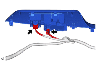
(c) w/ Rear Seat Side Airbag:
|
(1) Disconnect the 2 connectors to remove the power window regulator switch assembly with front armrest base upper panel. |
|
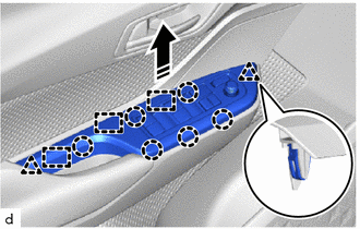
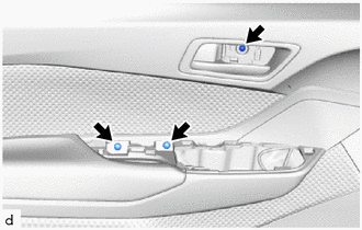
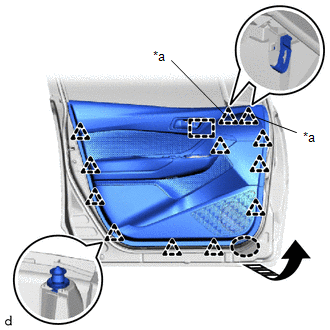
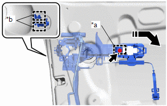
6. REMOVE FRONT DOOR TRIM BOARD SUB-ASSEMBLY
|
(a) Remove the 3 screws. |
|
(b) Disengage the clips (A), other clips and guide as shown in the illustration.
|
*a |
Clip (A) |
.png) |
Place Hands Here |
|
|
Remove in this Direction |
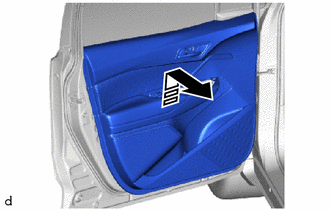
(c) Disengage the front door trim board sub-assembly with the front door glass inner weatherstrip and front door belt seal as shown in the illustration.
|
|
Remove in this Direction |
(d) w/ Illumination:
(1) Disconnect the connector.
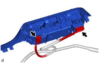
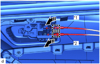
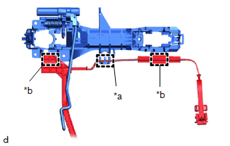
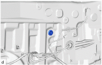
(e) Disengage the guides to disconnect the front door inside locking cable assembly and front door lock remote control cable assembly to remove the front door trim board sub-assembly as shown in the illustration.
|
*1 |
Front Door Inside Locking Cable Assembly |
|
*2 |
Front Door Lock Remote Control Cable Assembly |
|
|
Remove in this Direction |
7. REMOVE FRONT DOOR INSIDE HANDLE SUB-ASSEMBLY
(a) Disengage the claw and guides to remove the front door inside handle sub-assembly.
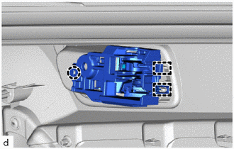
8. REMOVE NO. 1 INTERIOR ILLUMINATION LIGHT ASSEMBLY (w/ Illumination)
Click here
9. REMOVE FRONT DOOR LOWER FRAME BRACKET GARNISH
|
(a) Disengage the clips to remove the front door lower frame bracket garnish. |
|
10. REMOVE FRONT DOOR GLASS INNER WEATHERSTRIP
(a) Disengage the claws remove the front door glass inner weatherstrip with the front door belt seal as shown in the illustration.
|
|
Remove in this Direction |
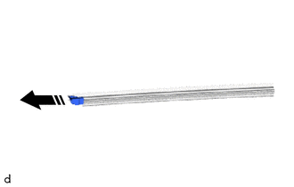
11. REMOVE FRONT DOOR BELT SEAL
(a) Remove the front door belt seal from the front door glass inner weatherstrip as shown in the illustration.
|
|
Remove in this Direction |
12. REMOVE FRONT DOOR VENT SEAL
|
(a) Remove the front door vent seal. |
|
13. REMOVE OUTER REAR VIEW MIRROR ASSEMBLY
Click here
14. REMOVE OUTER MIRROR PROTECTOR
(a) Remove the 2 screws.
|
|
Remove in this Direction |
(b) Disengage the claws to remove the outer mirror protector as shown in the illustration.
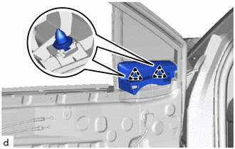
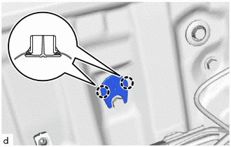
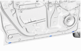
15. REMOVE FRONT DOOR SERVICE HOLE COVER
|
(a) Turn the 3 door weatherstrip clips 45° and remove it clips as shown in the illustration. |
|
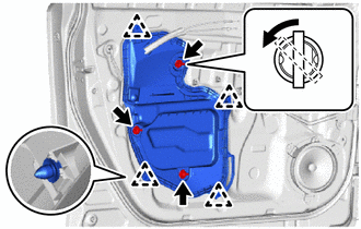
(b) Disengage the clips to remove the front door service hole cover.
16. REMOVE DOOR SIDE AIRBAG SENSOR (w/ Airbag Sensor)
Click here
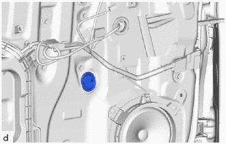
17. REMOVE FRONT DOOR GLASS SUB-ASSEMBLY
|
(a) Remove the hole plug. |
|
(b) for Driver Side:
(1) Connect the multiplex network master switch assembly.
(2) Connect the cable to the negative (-) battery terminal.
(3) Move the front door glass sub-assembly so that the door glass bolts can be seen.
(4) Disconnect the cable from the negative (-) battery terminal.
(5) Disconnect the multiplex network master switch assembly.
(c) for Front Passenger Side:
(1) Connect the power window regulator switch assembly.
(2) Connect the cable to the negative (-) battery terminal.
(3) Move the front door glass sub-assembly so that the door glass bolts can be seen.
(4) Disconnect the cable from the negative (-) battery terminal.
(5) Disconnect the power window regulator switch assembly.
|
(d) Remove the 2 bolts. NOTICE: After the bolts are removed, do not allow the front door glass sub-assembly to fall. |
|
(e) Remove the front door glass sub-assembly as shown in the illustration.
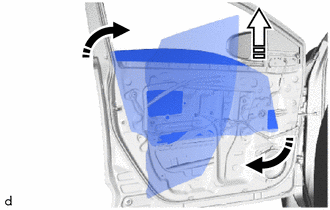
|
|
Remove in this Direction (1) |
.png) |
Remove in this Direction (2) |
NOTICE:
Do not damage the front door glass sub-assembly.
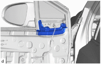
18. REMOVE NO. 2 FRONT DOOR SERVICE HOLE COVER
|
(a) Disengage the claws to remove the No. 2 front door service hole cover. |
|
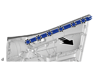
19. REMOVE FRONT DOOR WINDOW REGULATOR ASSEMBLY
|
(a) Disconnect the connector. |
|
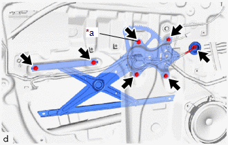
(b) Loosen the temporary bolt.
NOTICE:
Do not remove the temporary bolt. If the temporary bolt is removed, the front door window regulator assembly may fall and cause damage.
(c) Remove the 5 bolts and front door window regulator sub-assembly.
(d) Remove the temporary bolt from the front door window regulator assembly.
20. REMOVE DOOR FRAME UPPER GARNISH
|
(a) Disengage the guides to remove the door frame upper garnish. |
|
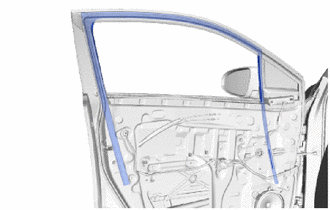
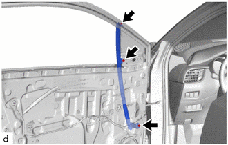
21. REMOVE FRONT DOOR GLASS RUN
|
(a) Remove the front door glass run. |
|
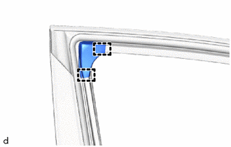
22. REMOVE FRONT DOOR FRONT LOWER FRAME SUB-ASSEMBLY
(a) Raise up the front door weatherstrip.
|
(b) Remove the screw. |
|
(c) Remove the 2 bolts and front door front lower frame sub-assembly.
(d) Install the front door weatherstrip.
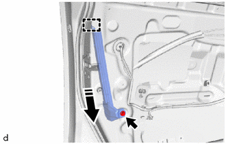
23. REMOVE FRONT DOOR REAR LOWER FRAME SUB-ASSEMBLY
(a) Remove the bolt.
|
|
Remove in this Direction |
(b) Disengage the guide to remove the front door rear lower frame sub-assembly as shown in the illustration.
24. REMOVE FRONT DOOR OUTSIDE HANDLE COVER (for Driver Side)
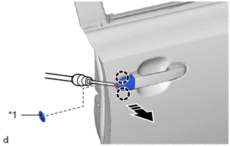
(a) Remove the hole plug.
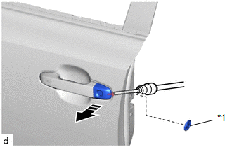
|
*1 |
Hole Plug |
|
|
Remove in this Direction |
(b) Using a T30 "TORX" socket wrench, loosen the screw.
(c) Remove the front door outside handle cover with front door lock cylinder assembly as shown in the illustration.
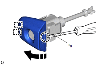
(d) Using a screwdriver with its tip wrapped in protective tape, disengage the claw and guides to remove the front door outside handle cover as shown in the illustration.
|
*a |
Protective Tape |
|
|
Remove in this Direction |
25. REMOVE FRONT DOOR OUTSIDE HANDLE COVER (for Front Passenger Side)
(a) Remove the hole plug.
|
*1 |
Hole Plug |
|
|
Remove in this Direction |
(b) Using a T30 "TORX" socket wrench, loosen the screw.
(c) Disengage the claws to remove the front door outside handle cover as shown in the illustration.
26. REMOVE FRONT DOOR OUTSIDE HANDLE ASSEMBLY
|
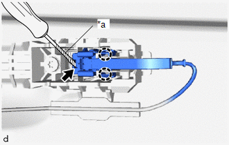
(a) w/ Smart Key System: (1) Disengage the claws. (2) Using a screwdriver with its tip wrapped in protective tape, disconnect the connector. |
|
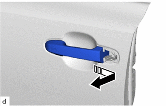
(b) Remove the front door outside handle assembly as shown in the illustration.
|
|
Remove in this Direction |
27. REMOVE FRONT DOOR FRONT OUTSIDE HANDLE PAD
(a) Disengage the claws and guide to remove the front door front outside handle pad as shown in the illustration.
|
|
Remove in this Direction |
28. REMOVE FRONT DOOR REAR OUTSIDE HANDLE PAD
(a) Disengage the guides to remove the front door rear outside handle pad as shown in the illustration.
|
|
Remove in this Direction |
29. REMOVE FRONT DOOR LOCK WITH MOTOR ASSEMBLY
Click here
30. REMOVE FRONT DOOR OUTSIDE HANDLE FRAME SUB-ASSEMBLY
(a) w/ Smart Key System:
(1) Using a T30 "TORX" socket wrench, loosen the screw.
|
*a |
Grommet |
|
*b |
Guide |
|
|
Remove in this Direction |
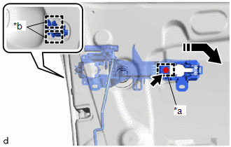
(2) Disengage the grommet and guides to separate the front door outside handle frame sub-assembly as shown in the illustration.
|
(3) Disengage the clamps and guide to remove the front door outside handle frame sub-assembly. |
|
(b) w/o Smart Key System:
(1) Using a T30 "TORX" socket wrench, loosen the screw.
|
*a |
Grommet |
|
*b |
Guide |
|
|
Remove in this Direction |
(2) Disengage the grommet and guides to remove the front door outside handle frame sub-assembly as shown in the illustration.
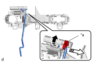
31. REMOVE FRONT DOOR LOCK OPEN ROD
(a) Disengage the snap to remove the front door lock open rod from the front door outside frame sub-assembly as shown in the illustration.
|
*a |
Snap |
|
|
Remove in this Direction (1) |
|
|
Remove in this Direction (2) |
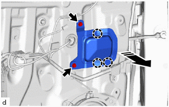
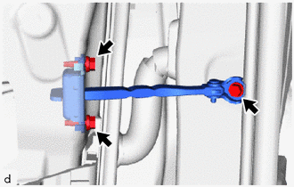
32. REMOVE FRONT DOOR CHECK ASSEMBLY
|
(a) Remove the 3 bolts and front door check assembly. |
|
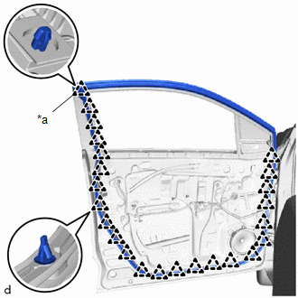
33. REMOVE FRONT DOOR WEATHERSTRIP
|
(a) Using a clip remover, disengage the clip (A) and other clips to remove the front door weatherstrip. |
|
34. REMOVE FRONT DOOR DUST PROOF SEAL
|
(a) Remove the 3 front door dust proof seals. |
|
35. REMOVE FRONT NO. 1 SPEAKER ASSEMBLY
Click here
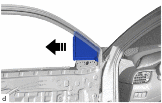
36. REMOVE FRONT DOOR FIX WINDOW GLASS
(a) Remove the front door fix window glass with front door fix window weatherstrip as shown in the illustration.
|
|
Remove in this Direction |
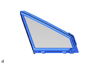
37. REMOVE FRONT DOOR FIX WINDOW WEATHERSTRIP
|
(a) Remove the front door fix window weatherstrip from the front door fix window glass. |
|
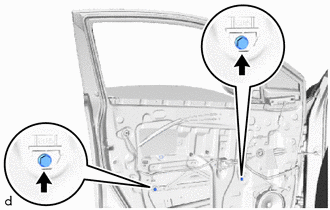
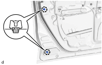
38. REMOVE FRONT DOOR PANEL CUSHION
|
(a) Using a clip remover, disengage the claws to remove the 2 front door panel cushions. |
|
39. REMOVE FRONT DOOR OUTSIDE MOULDING
Click here
40. REMOVE FRONT DOOR OUTSIDE MOULDING SUB-ASSEMBLY
Click here
41. REMOVE HOLE CAP
|
(a) Remove the hole cap. |
|
42. REMOVE FRONT DOOR BELT MOULDING ASSEMBLY
Click here
43. REMOVE FRONT DOOR SCUFF PLATE
Click here
44. REMOVE COWL SIDE TRIM BOARD
Click here
45. REMOVE FRONT DOOR FRONT WINDOW FRAME MOULDING
Click here
46. REMOVE FRONT DOOR UPPER WINDOW FRAME MOULDING
Click here
47. REMOVE NO. 4 FRONT DOOR STRIPE
Click here
48. REMOVE FRONT DOOR OUTSIDE STRIPE
Click here
49. REMOVE NO. 2 FRONT DOOR STRIPE
Click here
 Components
COMPONENTS
ILLUSTRATION
*A
w/ Illumination
*B
for Driver Side
*C
for Front Passenger Side
-
-
...
 Adjustment
ADJUSTMENT
CAUTION / NOTICE / HINT
*a
Centering Bolt
*b
Standard Bolt
HINT:
Use the same procedure for the RH side and LH side. ...
Other materials:
Toyota CH-R Service Manual > Window / Glass: Relay
On-vehicle Inspection
ON-VEHICLE INSPECTION
PROCEDURE
1. INSPECT DEFOGGER RELAY
(a) Check the resistance.
(1) Measure the resistance according to the value(s) in the table below.
Standard Resistance:
Tester Connection
Condition
...
Toyota CH-R Service Manual > Smart Key System(for Entry Function): Entry Exterior Alarm does not Sound
DESCRIPTION
The smart key system (for Entry Function) uses the wireless door lock buzzer
to perform various vehicle exterior warnings. When the conditions of each warning
are met, the certification ECU (smart key ECU assembly) sends a buzzer activation
request signal to the main body ECU (mul ...
Toyota C-HR (AX20) 2023-2026 Owner's Manual
Toyota CH-R Owners Manual
- For safety and security
- Instrument cluster
- Operation of each component
- Driving
- Interior features
- Maintenance and care
- When trouble arises
- Vehicle specifications
- For owners
Toyota CH-R Service Manual
- Introduction
- Maintenance
- Audio / Video
- Cellular Communication
- Navigation / Multi Info Display
- Park Assist / Monitoring
- Brake (front)
- Brake (rear)
- Brake Control / Dynamic Control Systems
- Brake System (other)
- Parking Brake
- Axle And Differential
- Drive Shaft / Propeller Shaft
- K114 Cvt
- 3zr-fae Battery / Charging
- Networking
- Power Distribution
- Power Assist Systems
- Steering Column
- Steering Gear / Linkage
- Alignment / Handling Diagnosis
- Front Suspension
- Rear Suspension
- Tire / Wheel
- Tire Pressure Monitoring
- Door / Hatch
- Exterior Panels / Trim
- Horn
- Lighting (ext)
- Mirror (ext)
- Window / Glass
- Wiper / Washer
- Door Lock
- Heating / Air Conditioning
- Interior Panels / Trim
- Lighting (int)
- Meter / Gauge / Display
- Mirror (int)
- Power Outlets (int)
- Pre-collision
- Seat
- Seat Belt
- Supplemental Restraint Systems
- Theft Deterrent / Keyless Entry

0.0084