Toyota CH-R Service Manual: Reassembly
REASSEMBLY
CAUTION / NOTICE / HINT
HINT:
- Use the same procedure for the RH side and LH side.
- The following procedure is for the LH side.
PROCEDURE
1. INSTALL NO. 2 FRONT DOOR STRIPE
Click here
.gif)
2. INSTALL FRONT DOOR OUTSIDE STRIPE
Click here
3. INSTALL NO. 4 FRONT DOOR STRIPE
Click here
4. INSTALL FRONT DOOR UPPER WINDOW FRAME MOULDING
Click here
5. INSTALL FRONT DOOR FRONT WINDOW FRAME MOULDING
Click here
6. INSTALL COWL SIDE TRIM BOARD
Click here
7. INSTALL FRONT DOOR SCUFF PLATE
Click here
8. INSTALL FRONT DOOR BELT MOULDING ASSEMBLY
Click here
9. INSTALL HOLE CAP
|
(a) Install the hole cap. |
|
.png)
10. INSTALL FRONT DOOR OUTSIDE MOULDING SUB-ASSEMBLY
Click here
11. INSTALL FRONT DOOR OUTSIDE MOULDING
Click here
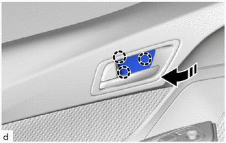
12. INSTALL FRONT DOOR PANEL CUSHION
|
(a) Engage the claws to install the 2 front door panel cushions. |
|
.png)
13. INSTALL FRONT DOOR FIX WINDOW WEATHERSTRIP
|
(a) Install the front door fix window weatherstrip to the front door fix window glass. |
|
.png)
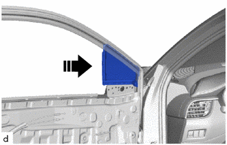
14. INSTALL FRONT DOOR FIX WINDOW GLASS
(a) Install the front door fix window glass with front door fix window weatherstrip as shown in the illustration.
.png) |
Install in this Direction |
15. INSTALL FRONT NO. 1 SPEAKER ASSEMBLY
Click here
16. INSTALL FRONT DOOR DUST PROOF SEAL
|
(a) Install the 3 front door dust proof seals. |
|
.png)
17. INSTALL FRONT DOOR WEATHERSTRIP
|
(a) Engage the clip (A) and other clip to install the front door weatherstrip. |
|
.png)
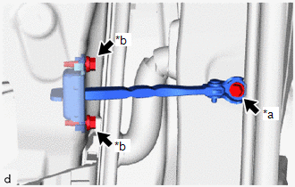
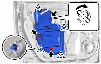
18. INSTALL FRONT DOOR CHECK ASSEMBLY
(a) Apply MP grease to the sliding parts of the front door check assembly.
(b) Clean the bolt hole in the vehicle body.
(c) Clean the threads of the bolt (A).
(d) Apply adhesive to the threads of the bolt (A).
Adhesive:
Toyota Genuine Adhesive 1324, Three Bond 1324 or equivalent
|
(e) Install the front door check assembly with the bolt (A) and 2 bolts (B). Torque: Bolt (A) : 30 N·m {306 kgf·cm, 22 ft·lbf} Bolt (B) : 5.5 N·m {56 kgf·cm, 49 in·lbf} |
|
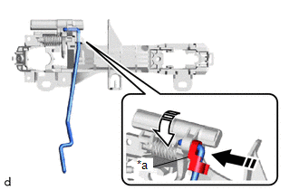
19. INSTALL FRONT DOOR LOCK OPEN ROD
(a) Engage the snap to install the front door lock open rod to the front door outside frame sub-assembly as shown in the illustration.
|
*a |
Snap |
|
|
Install in this Direction (1) |
.png) |
Install in this Direction (2) |
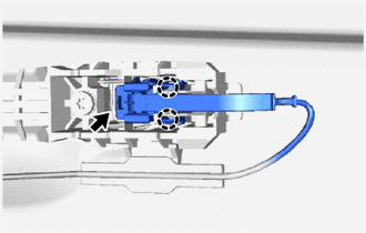
20. INSTALL FRONT DOOR OUTSIDE HANDLE FRAME SUB-ASSEMBLY
(a) Apply MP grease to the sliding parts on the front door outside handle frame sub-assembly.
(b) w/ Smart Key System:
|
(1) Engage the clamps and guide. |
|
(2) Engage the grommet and guides to install the front door outside handle frame sub-assembly as shown in the illustration.
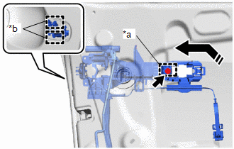
|
*a |
Grommet |
|
*b |
Guide |
|
|
Install in this Direction |
(3) Using a T30 "TORX" socket wrench, tighten the screw.
Torque:
4.0 N·m {41 kgf·cm, 35 in·lbf}
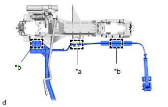
(c) w/o Smart Key System:
(1) Engage the grommet and guides to install the front door outside handle frame sub-assembly as shown in the illustration.
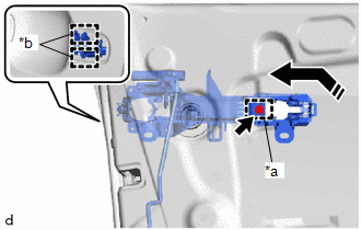
|
*a |
Grommet |
|
*b |
Guide |
|
|
Install in this Direction |
(2) Using a T30 "TORX" socket wrench, tighten the screw.
Torque:
4.0 N·m {41 kgf·cm, 35 in·lbf}
21. INSTALL FRONT DOOR LOCK WITH MOTOR ASSEMBLY
Click here
22. INSTALL FRONT DOOR REAR OUTSIDE HANDLE PAD
(a) Engage the guides to install the front door rear outside handle pad as shown in the illustration.
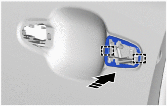
|
|
Install in this Direction |
23. INSTALL FRONT DOOR FRONT OUTSIDE HANDLE PAD
(a) Engage the guide and claws to install the front door front outside handle pad as shown in the illustration.
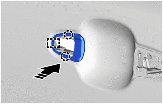
|
|
Install in this Direction |
24. INSTALL FRONT DOOR OUTSIDE HANDLE ASSEMBLY
(a) Install the front door outside handle assembly as shown in the illustration.
|
|
Install in this Direction |
|
(b) w/ Smart Key System: (1) Connect the connector. (2) Engage the claws. |
|
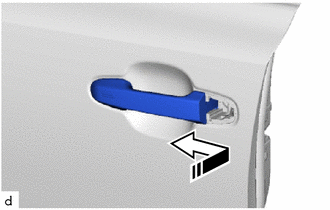
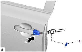
25. INSTALL FRONT DOOR OUTSIDE HANDLE COVER (for Front Passenger Side)
(a) Engage the claws to install the front door outside handle cover as shown in the illustration.
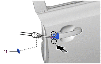
|
*1 |
Hole Plug |
|
|
Remove in this Direction |
(b) Using a T30 "TORX" socket wrench, tighten the screw.
Torque:
4.0 N·m {41 kgf·cm, 35 in·lbf}
(c) Install the hole plug.
26. INSTALL FRONT DOOR OUTSIDE HANDLE COVER (for Driver Side)
(a) Engage the guides and claw to install the front door outside handle cover as shown in the illustration.
|
|
Install in this Direction |
(b) Apply MP grease to the sliding area of the front door lock cylinder assembly.
(c) Install the front door outside handle cover with lock cylinder assembly as shown in the illustration.
|
*1 |
Hole Plug |
|
|
Install in this Direction |
HINT:
Check that the front door lock cylinder assembly is inserted into the front door lock with motor assembly.
(d) Using a T30 "TORX" socket wrench, tighten the screw.
Torque:
4.0 N·m {41 kgf·cm, 35 in·lbf}
(e) Install the hole plug.
27. INSTALL FRONT DOOR REAR LOWER FRAME SUB-ASSEMBLY
(a) Engage the guide to install the front door rear lower frame sub-assembly.
|
|
Install in this Direction |
(b) Install the bolt.
Torque:
8.5 N·m {87 kgf·cm, 75 in·lbf}
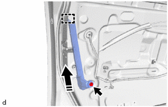
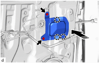
28. INSTALL FRONT DOOR FRONT LOWER FRAME SUB-ASSEMBLY
|
(a) Install the front door front lower frame sub-assembly with the 2 bolts. Torque: 8.5 N·m {87 kgf·cm, 75 in·lbf} |
|
.png)
(b) Raise up the front door weatherstrip.
(c) Install the screw.
(d) Install the front door weatherstrip.
29. INSTALL FRONT DOOR GLASS RUN
|
(a) Install the front door glass run. |
|
.png)
30. INSTALL DOOR FRAME UPPER GARNISH
|
(a) Engage the guides to install the door frame upper garnish. |
|
.png)
31. INSTALL FRONT DOOR WINDOW REGULATOR ASSEMBLY
(a) Apply MP grease to the sliding parts of the front door window regulator assembly.
|
(b) Temporarily install the temporary bolt to the front door window regulator assembly. |
|
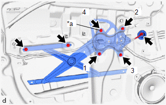
(c) Temporarily install the front door window regulator assembly with the 5 bolts.
(d) Tighten the temporary bolt and 3 bolts to install the front door window regulator assembly.
Torque:
8.0 N·m {82 kgf·cm, 71 in·lbf}
HINT:
Tighten the bolts in the order shown in the illustration.
(e) Tighten the 2 bolts.
Torque:
8.0 N·m {82 kgf·cm, 71 in·lbf}
(f) Connect the connector.
32. INSTALL NO. 2 FRONT DOOR SERVICE HOLE COVER
|
(a) Engage the claws to install the No. 2 front door service hole cover. |
|
.png)
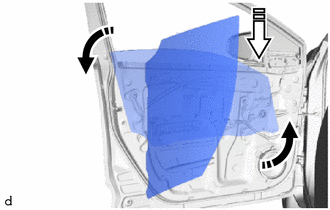
33. INSTALL FRONT DOOR GLASS SUB-ASSEMBLY
(a) for Driver Side:
(1) Connect the power window regulator master switch assembly.
(2) Connect the cable to the negative (-) battery terminal.
(3) Move the front door glass sub-assembly so that the door glass bolt holes can be seen.
(4) Disconnect the cable from the negative (-) battery terminal.
(5) Disconnect the power window regulator master switch assembly.
(b) for Front Passenger Side:
(1) Connect the power window regulator switch assembly.
(2) Connect the cable to the negative (-) battery terminal.
(3) Move the front door glass sub-assembly so that the door glass bolt holes can be seen.
(4) Disconnect the cable from the negative (-) battery terminal.
(5) Disconnect the power window regulator switch assembly.
(c) Insert the front door glass sub-assembly into the front door panel along the front door glass run as shown in the illustration.
|
|
Install in this Direction (1) |
|
|
Install in this Direction (2) |
NOTICE:
Be careful not to damage the front door glass sub-assembly.
|
(d) Install the front door glass sub-assembly with the 2 bolts. Torque: 8.0 N·m {82 kgf·cm, 71 in·lbf} |
|
.png)
|
(e) Install the hole plug. |
|
.png)
34. INSTALL DOOR SIDE AIRBAG SENSOR (w/ Airbag Sensor)
Click here
35. INSTALL FRONT DOOR SERVICE HOLE COVER
|
(a) Engage the clips to install the front door service hole cover. |
|
(b) Insert the 3 front door weatherstrip clips and turn them 45° as shown in the illustration.
36. INSTALL OUTER MIRROR PROTECTOR
(a) Engage the claws to install the outer mirror protector as shown in the illustration.
|
|
Install in this Direction |
(b) Install the 2 screws.
37. INSTALL OUTER REAR VIEW MIRROR ASSEMBLY
Click here
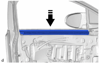
38. INSTALL FRONT DOOR VENT SEAL
|
(a) Install the front door vent seal. |
|
.png)
39. INSTALL FRONT DOOR BELT SEAL
(a) Install the front door belt seal to the front door glass inner weatherstrip as shown in the illustration.
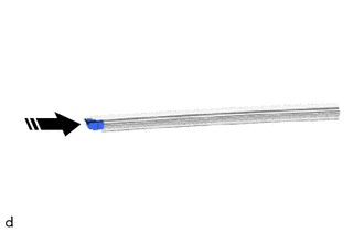
|
|
Install in this Direction |
40. INSTALL FRONT DOOR GLASS INNER WEATHERSTRIP
(a) Install the front door glass inner weatherstrip with the front door belt seal as shown in the illustration.
|
|
Install in this Direction |
41. INSTALL FRONT DOOR LOWER FRAME BRACKET GARNISH
|
(a) Engage the clips to install the front door lower frame bracket garnish. |
|
.png)
42. INSTALL NO. 1 INTERIOR ILLUMINATION LIGHT ASSEMBLY (w/ Illumination)
Click here
43. INSTALL FRONT DOOR INSIDE HANDLE SUB-ASSEMBLY
|
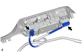
(a) Engage the claw and guides to install the front door inside handle sub-assembly. |
|
.png)
44. INSTALL FRONT DOOR TRIM BOARD SUB-ASSEMBLY
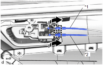
(a) Engage the guides to connect the front door lock remote control cable assembly and front door inside locking cable assembly as shown in the illustration.
|
*1 |
Front Door Inside Locking Cable Assembly |
|
*2 |
Front Door Lock Remote Control Cable Assembly |
|
|
Install in this Direction |
(b) w/ Illumination:
(1) Connect the connector.
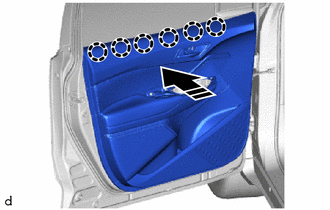
(c) Engage the claws as shown in the illustration.
|
|
Install in this Direction |
|
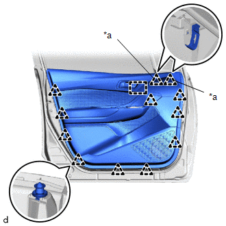
(d) Engage the clip (A), other clips and guide to install the front door trim board sub-assembly. |
|
|
(e) Install the 3 screws. |
|
.png)
45. INSTALL MULTIPLEX NETWORK MASTER SWITCH ASSEMBLY WITH FRONT ARMREST BASE UPPER PANEL (for Driver Side)
|
(a) Connect the 2 connectors. |
|
(b) Engage the guides, clips and claws to install the multiplex network master switch assembly with front door upper armrest base panel as shown in the illustration.
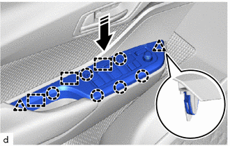
|
|
Install in this Direction |
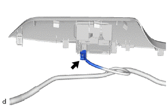
46. INSTALL POWER WINDOW REGULATOR SWITCH ASSEMBLY WITH FRONT ARMREST BASE UPPER PANEL (for Front Passenger Side)
(a) w/o Rear Seat Side Airbag:
|
(1) Connect the connector. |
|
(b) w/ Rear Seat Side Airbag:
|
(1) Connect the 2 connectors. |
|
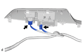
(c) Engage the guides, clips and claws to install the power window regulator switch assembly with front door upper armrest base panel as shown in the illustration.
|
|
Install in this Direction |
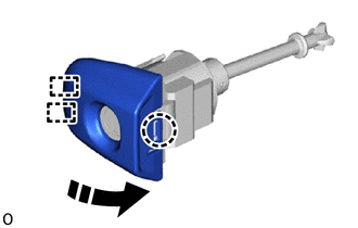
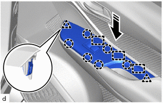
47. INSTALL FRONT DOOR INSIDE HANDLE BEZEL PLUG
(a) Engage the claws to install the front door inside handle bezel plug as shown in the illustration.
|
|
Install in this Direction |
48. CONNECT CABLE TO NEGATIVE BATTERY TERMINAL
Click here
NOTICE:
When disconnecting the cable, some systems need to be initialized after the cable is reconnected.
Click here
49. INITIALIZE POWER WINDOW CONTROL SYSTEM
Click here
50. INSPECT POWER WINDOW OPERATION
Click here
51. INSPECT SRS WARNING LIGHT (w/ Airbag Sensor)
Click here
 Adjustment
ADJUSTMENT
CAUTION / NOTICE / HINT
*a
Centering Bolt
*b
Standard Bolt
HINT:
Use the same procedure for the RH side and LH side. ...
 Front Door Opening Trim Weatherstrip
Components
COMPONENTS
ILLUSTRATION
*1
COWL SIDE TRIM BOARD
*2
FRONT DOOR OPENING TRIM WEATHERSTRIP
*3
FRONT DOOR SCUFF PL ...
Other materials:
Toyota CH-R Service Manual > Transmission Control Cable: Adjustment
ADJUSTMENT
PROCEDURE
1. SECURE VEHICLE
(a) Fully apply the parking brake and chock a wheel.
CAUTION:
Make sure to apply the parking brake and chock a wheel before performing
this procedure.
If the vehicle is not secure and the shift lever is moved to N, the
vehicle may sudd ...
Toyota CH-R Service Manual > Knee Airbag Assembly: Components
COMPONENTS
ILLUSTRATION
*A
for TMMT Made
*B
for TMC Made
*1
INSTRUMENT CLUSTER FINISH PANEL GARNISH ASSEMBLY
*2
INSTRUMENT PANEL LOWER CENTER FINISH PANEL
*3
LOWER NO. 1 INST ...
Toyota C-HR (AX20) 2023-2026 Owner's Manual
Toyota CH-R Owners Manual
- For safety and security
- Instrument cluster
- Operation of each component
- Driving
- Interior features
- Maintenance and care
- When trouble arises
- Vehicle specifications
- For owners
Toyota CH-R Service Manual
- Introduction
- Maintenance
- Audio / Video
- Cellular Communication
- Navigation / Multi Info Display
- Park Assist / Monitoring
- Brake (front)
- Brake (rear)
- Brake Control / Dynamic Control Systems
- Brake System (other)
- Parking Brake
- Axle And Differential
- Drive Shaft / Propeller Shaft
- K114 Cvt
- 3zr-fae Battery / Charging
- Networking
- Power Distribution
- Power Assist Systems
- Steering Column
- Steering Gear / Linkage
- Alignment / Handling Diagnosis
- Front Suspension
- Rear Suspension
- Tire / Wheel
- Tire Pressure Monitoring
- Door / Hatch
- Exterior Panels / Trim
- Horn
- Lighting (ext)
- Mirror (ext)
- Window / Glass
- Wiper / Washer
- Door Lock
- Heating / Air Conditioning
- Interior Panels / Trim
- Lighting (int)
- Meter / Gauge / Display
- Mirror (int)
- Power Outlets (int)
- Pre-collision
- Seat
- Seat Belt
- Supplemental Restraint Systems
- Theft Deterrent / Keyless Entry

0.0108