Toyota CH-R Service Manual: Terminals Of Ecu
TERMINALS OF ECU
CHECK INSTRUMENT PANEL JUNCTION BLOCK ASSEMBLY AND MAIN BODY ECU (MULTIPLEX NETWORK BODY ECU)
.png)
|
*A |
Main Body ECU (Multiplex Network Body ECU) with 2 Connectors |
- |
- |
|
*1 |
Main Body ECU (Multiplex Network Body ECU) |
- |
- |
|
*a |
2 Connectors |
- |
- |
.png)
|
*A |
Main Body ECU (Multiplex Network Body ECU) with 1 Connector |
- |
- |
|
*1 |
Main Body ECU (Multiplex Network Body ECU) |
- |
- |
|
*a |
1 Connector |
- |
- |
(a) Remove the main body ECU (multiplex network body ECU) from the instrument panel junction block assembly.
Click here
.gif)
(b) Reconnect the instrument panel junction block assembly connectors.
(c) Measure the voltage and resistance according to the value(s) in the table below.
|
Terminal No. (Symbol) |
Wiring Color |
Terminal Description |
Condition |
Specified Condition |
|---|---|---|---|---|
|
MB-11 (GND1) - Body ground |
- |
Ground |
Always |
Below 1 Ω |
|
MB-30 (ACC) - Body ground |
- |
ACC power supply |
Ignition switch ACC |
11 to 14 V |
|
MB-30 (ACC) - Body ground |
- |
ACC power supply |
Ignition switch off |
Below 1 V |
|
MB-31 (BECU) - Body ground |
- |
Battery power supply |
Always |
11 to 14 V |
|
MB-32 (IG) - Body ground |
- |
IG power supply |
Ignition switch ON |
11 to 14 V |
|
MB-32 (IG) - Body ground |
- |
IG power supply |
Ignition switch off |
Below 1 V |
(d) Install the main body ECU (multiplex network body ECU) to the instrument panel junction block assembly.
Click here
(e) Measure the voltage and check for pulses according to the value(s) in the table below.
|
Terminal No. (Symbol) |
Wiring Color |
Terminal Description |
Condition |
Specified Condition |
|---|---|---|---|---|
|
F15-2 (UL3) - Body ground |
L - Body ground |
Driver door key-linked unlock input |
Driver door key cylinder in neutral position → on (unlock) |
Pulse generation → Below 1 V |
|
F15-29 (L2) - Body ground |
G - Body ground |
Driver door key-linked lock input |
Driver door key cylinder in neutral position → on (lock) |
Pulse generation → Below 1 V |
|
F15-6 (FLCY) - Body ground |
R - Body ground |
Front door courtesy light switch (for LH) input |
Front door LH open |
Below 1 V |
|
F15-6 (FLCY) - Body ground |
R - Body ground |
Front door courtesy light switch (for LH) input |
Front door LH closed |
Pulse generation |
|
F15-27 (FRCY) - Body ground |
BR - Body ground |
Front door courtesy light switch (for RH) input |
Front door RH open |
Below 1 V |
|
F15-27 (FRCY) - Body ground |
BR - Body ground |
Front door courtesy light switch (for RH) input |
Front door RH closed |
Pulse generation |
|
3H-8 (ACT-) - Body ground |
LA-B - Body ground |
Door lock motor unlock drive output |
Door control switch or driver door key cylinder off → on (unlock) |
Below 1 V → 11 to 14 V → Below 1 V |
|
3H-9 (ACT-) - Body ground |
B - Body ground |
Door lock motor unlock drive output |
Door control switch or driver door key cylinder off → on (unlock) |
Below 1 V → 11 to 14 V → Below 1 V |
|
3H-6 (ACT+) - Body ground |
R - Body ground |
Door lock motor lock drive output |
Door control switch or driver door key cylinder off → on (lock) |
Below 1 V → 11 to 14 V → Below 1 V |
|
3H-18 (ACT+) - Body ground |
R - Body ground |
Door lock motor lock drive output |
Door control switch or driver door key cylinder off → on (lock) |
Below 1 V → 11 to 14 V → Below 1 V |
|
3D-4 (ACTD) - Body ground |
B - Body ground |
Door lock motor unlock drive output |
Door control switch or driver door key cylinder off → on (unlock) |
Below 1 V → 11 to 14 V → Below 1 V |
|
3H-24 (LCTY) - Body ground |
BR - Body ground |
Rear door courtesy light switch (for LH) input |
Rear door LH open |
Below 1 V |
|
3H-24 (LCTY) - Body ground |
BR - Body ground |
Rear door courtesy light switch (for LH) input |
Rear door LH closed |
Pulse generation |
|
3A-31 (RCTY) - Body ground |
BR - Body ground |
Rear door courtesy light switch (for RH) input |
Rear door RH open |
Below 1 V |
|
3A-31 (RCTY) - Body ground |
BR - Body ground |
Rear door courtesy light switch (for RH) input |
Rear door RH closed |
Pulse generation |
|
3H-34 (BCTY) - Body ground |
SB - Body ground |
Back door courtesy light switch input |
Back door open |
Below 1 V |
|
3H-34 (BCTY) - Body ground |
SB - Body ground |
Back door courtesy light switch input |
Back door closed |
Pulse generation |
|
3H-20 (TR+) - Body ground |
Y - Body ground |
Back door lock motor drive output |
Back door closed → open |
Below 1 V → 11 to 14 V → Below 1 V |
|
3D-14 (LSR) - Body ground |
LG - Body ground |
Rear door LH/RH unlock detection switch input |
Rear door LH or RH unlocked |
Below 1 V |
|
3D-14 (LSR) - Body ground |
LG - Body ground |
Rear door LH/RH unlock detection switch input |
Rear door LH and RH locked |
Pulse generation |
|
3D-12 (LSFR) - Body ground |
GR - Body ground |
Front door RH unlock detection switch input |
Front door RH unlocked |
Below 1 V |
|
3D-12 (LSFR) - Body ground |
GR - Body ground |
Front door RH unlock detection switch input |
Front door RH locked |
Pulse generation |
|
3D-13 (LSFL) - Body ground |
B - Body ground |
Front door LH unlock detection switch input |
Front door LH unlocked |
Below 1 V |
|
3D-13 (LSFL) - Body ground |
B - Body ground |
Front door LH unlock detection switch input |
Front door LH locked |
Pulse generation |
|
3A-39 (UL1) - Body ground |
SB - Body ground |
Door control switch input |
Door control switch locked |
Below 1 V |
|
3A-39 (UL1) - Body ground |
SB - Body ground |
Door control switch input |
Door control switch off |
Pulse generation |
|
3D-16 (L1) - Body ground |
B - Body ground |
Door control switch input |
Door control switch unlocked |
Below 1 V |
|
3D-16 (L1) - Body ground |
B - Body ground |
Door control switch input |
Door control switch off |
Pulse generation |
|
F15-18 (BDSU) - Body ground*1 |
LG - Body ground |
Back door opener switch input |
Back door opener switch pushed |
Below 1 V |
|
F15-18 (BDSU) - Body ground*1 |
LG - Body ground |
Back door opener switch input |
Back door opener switch not pushed |
Pulse generation |
*1: w/o Smart Key System
CHECK CERTIFICATION ECU (SMART KEY ECU ASSEMBLY) (w/ Smart Key System)
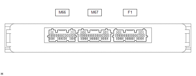
(a) Disconnect the F1 certification ECU (smart key ECU assembly) connector.
(b) Measure the voltage and resistance according to the value(s) in the table below.
|
Terminal No. (Symbol) |
Wiring Color |
Terminal Description |
Condition |
Specified Condition |
|---|---|---|---|---|
|
F1-4 (+B) - Body ground |
L - Body ground |
Battery power supply |
Always |
11 to 14 V |
|
F1-18 (E) - Body ground |
W-B - Body ground |
Ground |
Always |
Below 1 Ω |
(c) Reconnect the M67 certification ECU (smart key ECU assembly) connector.
(d) Check for pulses according to the value(s) in the table below.
|
Terminal No. (Symbol) |
Wiring Color |
Terminal Description |
Condition |
Specified Condition |
|---|---|---|---|---|
|
M67-26 (TSW5) - Body ground |
LG - Body ground |
Back door opener switch input |
Back door opener switch assembly (open switch) off → on |
Below 1 V → Pulse generation |
CHECK DOUBLE LOCK DOOR CONTROL RELAY ASSEMBLY (w/o Toyota Safety Sense P)

(a) Disconnect the F14 double lock door control relay assembly connector.
(b) Measure the voltage and resistance according to the value(s) in the table below.
|
Terminal No. (Symbol) |
Wiring Color |
Terminal Description |
Condition |
Specified Condition |
|---|---|---|---|---|
|
F14-12 (+B) - Body ground |
BE - Body ground |
Battery power supply |
Ignition switch off |
11 to 14 V |
|
F14-11 (CPUB) - Body ground |
SB - Body ground |
Battery power supply |
Ignition switch off |
11 to 14 V |
|
F14-7 (GND) - Body ground |
LA - Body ground |
Ground |
Always |
Below 1 Ω |
(c) Reconnect the F14 double lock door control relay assembly connector.
(d) Measure the voltage and check for pulses according to the value(s) in the table below.
|
Terminal No. (Symbol) |
Wiring Color |
Terminal Description |
Condition |
Specified Condition |
|---|---|---|---|---|
|
F14-8 (ACTS) - Body ground |
LG - Body ground |
All door double lock motor set on output |
Double lock unset |
Below 1 V |
|
F14-8 (ACTS) - Body ground |
LG - Body ground |
All door double lock motor set on output |
Double lock set |
11 to 14 V |
|
F14-1 (ACTR) - Body ground |
GR - Body ground |
All door double lock motor set off output |
Double lock set |
Below 1 V |
|
F14-1 (ACTR) - Body ground |
GR - Body ground |
All door double lock motor set off output |
Double lock unset |
11 to 14 V |
|
F14-6 (DLPD) - Body ground |
Y - Body ground |
Front RH double lock position switch input |
Double lock unset |
Pulse generation |
|
F14-6 (DLPD) - Body ground |
Y - Body ground |
Front RH double lock position switch input |
Double lock set |
Below 1 V |
|
F14-5 (DLPP) - Body ground |
V - Body ground |
Front LH double lock position switch input |
Double lock unset |
Pulse generation |
|
F14-5 (DLPP) - Body ground |
V - Body ground |
Front LH double lock position switch input |
Double lock set |
Below 1 V |
|
F14-4 (DLPR) - Body ground |
B - Body ground |
Rear RH double lock position switch input |
Double lock unset |
Pulse generation |
|
F14-4 (DLPR) - Body ground |
B - Body ground |
Rear RH double lock position switch input |
Double lock set |
Below 1 V |
|
F14-3 (DLPL) - Body ground |
L - Body ground |
Rear LH double lock position switch input |
Double lock unset |
Pulse generation |
|
F14-3 (DLPL) - Body ground |
L - Body ground |
Rear LH double lock position switch input |
Double lock set |
Below 1 V |
 Problem Symptoms Table
PROBLEM SYMPTOMS TABLE
HINT:
Use the table below to help determine the cause of problem symptoms.
If multiple suspected areas are listed, the potential causes of the symptoms
are lis ...
 Data List / Active Test
DATA LIST / ACTIVE TEST
DATA LIST
HINT:
Using the Techstream to read the Data List allows the values or states of switches,
sensors, actuators and other items to be read without removing any part ...
Other materials:
Toyota CH-R Service Manual > Brake (front): Front Disc Brake Pad
Components
COMPONENTS
ILLUSTRATION
*1
FRONT DISC BRAKE ANTI-SQUEAL SHIM KIT
*2
FRONT DISC BRAKE CYLINDER ASSEMBLY
*3
FRONT DISC BRAKE PAD
*4
FRONT BRAKE PAD RADIAL SPRING
*5
...
Toyota CH-R Service Manual > Brake Control / Dynamic Control Systems: Vsc Off Switch
Components
COMPONENTS
ILLUSTRATION
*1
VSC OFF SWITCH (ELECTRIC PARKING BRAKE SWITCH ASSEMBLY)
-
-
Inspection
INSPECTION
PROCEDURE
1. INSPECT VSC OFF SWITCH (ELECTRIC PARKING BRAKE SWITCH ASSEMBLY) (for LHD)
(a) Check the resistance.
...
Toyota C-HR (AX20) 2023-2026 Owner's Manual
Toyota CH-R Owners Manual
- For safety and security
- Instrument cluster
- Operation of each component
- Driving
- Interior features
- Maintenance and care
- When trouble arises
- Vehicle specifications
- For owners
Toyota CH-R Service Manual
- Introduction
- Maintenance
- Audio / Video
- Cellular Communication
- Navigation / Multi Info Display
- Park Assist / Monitoring
- Brake (front)
- Brake (rear)
- Brake Control / Dynamic Control Systems
- Brake System (other)
- Parking Brake
- Axle And Differential
- Drive Shaft / Propeller Shaft
- K114 Cvt
- 3zr-fae Battery / Charging
- Networking
- Power Distribution
- Power Assist Systems
- Steering Column
- Steering Gear / Linkage
- Alignment / Handling Diagnosis
- Front Suspension
- Rear Suspension
- Tire / Wheel
- Tire Pressure Monitoring
- Door / Hatch
- Exterior Panels / Trim
- Horn
- Lighting (ext)
- Mirror (ext)
- Window / Glass
- Wiper / Washer
- Door Lock
- Heating / Air Conditioning
- Interior Panels / Trim
- Lighting (int)
- Meter / Gauge / Display
- Mirror (int)
- Power Outlets (int)
- Pre-collision
- Seat
- Seat Belt
- Supplemental Restraint Systems
- Theft Deterrent / Keyless Entry

0.0078