Toyota CH-R Service Manual: Removal
REMOVAL
CAUTION / NOTICE / HINT
NOTICE:
- Immediately after installing the brake pads, the braking performance may be reduced. Always perform a road test in a safe place while paying attention to the surroundings.
- After replacing the front disc brake pads, always perform a road test to check the braking performance and check for vibrations.
HINT:
- Use the same procedure for the RH side and LH side.
- The following procedure is for the LH side.
PROCEDURE
1. REMOVE FRONT WHEEL
Click here
.gif)
2. DRAIN BRAKE FLUID
NOTICE:
If brake fluid leaks onto any painted surface, immediately wash it off.
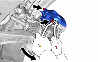
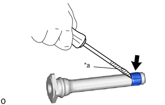
3. DISCONNECT FRONT FLEXIBLE HOSE
|
(a) Remove the union bolt and gasket, and disconnect the front flexible hose from the front disc brake cylinder assembly. |
|
.png)
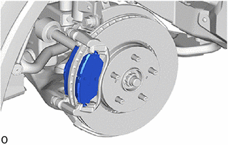
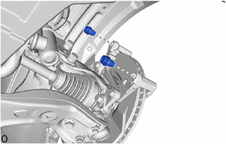
4. REMOVE FRONT DISC BRAKE CYLINDER ASSEMBLY
|
(a) Hold the 2 front disc brake cylinder slide pins and remove the 2 bolts and front disc brake cylinder assembly. |
|
5. REMOVE FRONT DISC BRAKE PAD
|
(a) Remove the 2 front disc brake pads from the front disc brake cylinder mounting. |
|
6. REMOVE FRONT DISC BRAKE ANTI-SQUEAL SHIM KIT
Click here
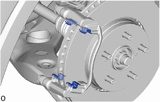
7. REMOVE FRONT DISC BRAKE PAD SUPPORT PLATE
|
(a) Remove the 4 front disc brake pad support plates from the front disc brake cylinder mounting. NOTICE: Each front disc brake pad support plate has a different shape. Be sure to put an identification mark on each front disc brake pad support plate so that it can be reinstalled to its original position. |
|
8. REMOVE FRONT DISC BRAKE CYLINDER SLIDE PIN
|
(a) Remove the 2 front disc brake cylinder slide pins from the front disc brake cylinder mounting. |
|
|
(b) Using a screwdriver with its tip wrapped with protective tape, remove the front disc brake cylinder slide bushing from the front disc brake cylinder slide pin (lower side). NOTICE: Do not damage the front disc brake cylinder slide pin. |
|
9. REMOVE FRONT DISC BRAKE BUSHING DUST BOOT
|
(a) Remove the 2 front disc brake bushing dust boots from the front disc brake cylinder mounting. |
|
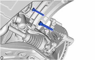
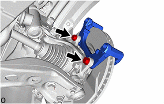
10. REMOVE FRONT DISC BRAKE CYLINDER MOUNTING
|
(a) Remove the 2 bolts and front disc brake cylinder mounting from the steering knuckle. |
|
11. REMOVE FRONT DISC
|
(a) Put matchmarks on the front disc and the front axle hub sub-assembly. HINT: If the front disc needs to be replaced, matchmarks do not have to be put. |
|
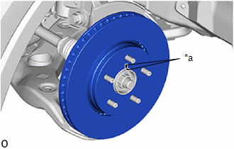
(b) Remove the front disc.
 Components
COMPONENTS
ILLUSTRATION
*1
FRONT DISC BRAKE ANTI-SQUEAL SHIM KIT
*2
FRONT DISC BRAKE CYLINDER ASSEMBLY
*3
FRONT DISC BRAKE P ...
 Disassembly
DISASSEMBLY
PROCEDURE
1. REMOVE FRONT DISC BRAKE PISTON
(a) Place a piece of cloth between the front disc brake piston and front
disc brake cylinder assembly.
...
Other materials:
Toyota CH-R Service Manual > Steering Lock System: Terminals Of Ecu
TERMINALS OF ECU
TERMINAL INSPECTION
*a
Component without harness connected
(Steering Lock ECU (Steering Lock Actuator or Upper Bracket Assembly))
-
-
(a) Measure the voltage and resistance according to the value(s) in the table
below.
...
Toyota CH-R Service Manual > Air Conditioning System(for Automatic Air Conditioning System With Top-mounted
Air Conditioner Pressure Sensor): Room Temperature Sensor Circuit (B1411)
DESCRIPTION
The cooler thermistor (room temperature sensor) is installed in the instrument
panel to detect the cabin temperature, which is used to control the air conditioning
system. The resistance of the cooler thermistor (room temperature sensor) changes
in accordance with the cabin temper ...
Toyota C-HR (AX20) 2023-2026 Owner's Manual
Toyota CH-R Owners Manual
- For safety and security
- Instrument cluster
- Operation of each component
- Driving
- Interior features
- Maintenance and care
- When trouble arises
- Vehicle specifications
- For owners
Toyota CH-R Service Manual
- Introduction
- Maintenance
- Audio / Video
- Cellular Communication
- Navigation / Multi Info Display
- Park Assist / Monitoring
- Brake (front)
- Brake (rear)
- Brake Control / Dynamic Control Systems
- Brake System (other)
- Parking Brake
- Axle And Differential
- Drive Shaft / Propeller Shaft
- K114 Cvt
- 3zr-fae Battery / Charging
- Networking
- Power Distribution
- Power Assist Systems
- Steering Column
- Steering Gear / Linkage
- Alignment / Handling Diagnosis
- Front Suspension
- Rear Suspension
- Tire / Wheel
- Tire Pressure Monitoring
- Door / Hatch
- Exterior Panels / Trim
- Horn
- Lighting (ext)
- Mirror (ext)
- Window / Glass
- Wiper / Washer
- Door Lock
- Heating / Air Conditioning
- Interior Panels / Trim
- Lighting (int)
- Meter / Gauge / Display
- Mirror (int)
- Power Outlets (int)
- Pre-collision
- Seat
- Seat Belt
- Supplemental Restraint Systems
- Theft Deterrent / Keyless Entry

0.0131