Toyota CH-R Service Manual: Front Door Opening Trim Weatherstrip
Components
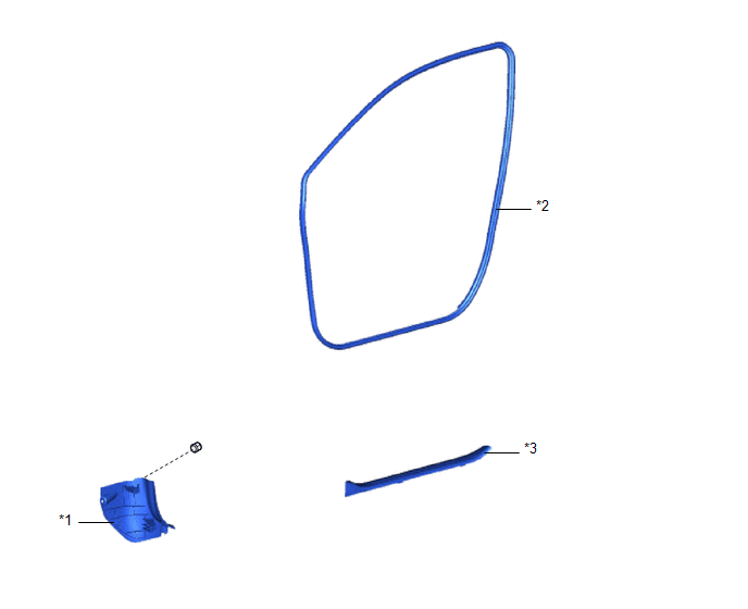
COMPONENTS
ILLUSTRATION
|
*1 |
COWL SIDE TRIM BOARD |
*2 |
FRONT DOOR OPENING TRIM WEATHERSTRIP |
|
*3 |
FRONT DOOR SCUFF PLATE |
- |
- |
Removal
REMOVAL
CAUTION / NOTICE / HINT
HINT:
- Use the same procedure for the RH side and LH side.
- The following procedure is for the LH side.
PROCEDURE
1. REMOVE FRONT DOOR SCUFF PLATE
Click here
.gif)
2. REMOVE COWL SIDE TRIM BOARD
Click here
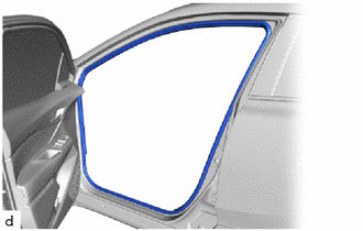
3. REMOVE FRONT DOOR OPENING TRIM WEATHERSTRIP
|
(a) Remove the front door opening trim weatherstrip. |
|
Installation
INSTALLATION
CAUTION / NOTICE / HINT
HINT:
- Use the same procedure for the RH side and LH side.
- The following procedure is for the LH side.
PROCEDURE
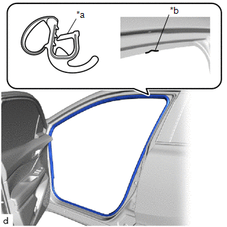
1. INSTALL FRONT DOOR OPENING TRIM WEATHERSTRIP
|
(a) Align the paint mark on the front door opening trim weatherstrip with the mark position on the vehicle and install the front door opening trim weatherstrip as shown in the illustration. Paint Mark:
NOTICE:
HINT: To easily install the weatherstrip, first install the area with the paint mark as shown in the illustration. Then install the part toward the corners and push any excess length into the corners. |
|
2. INSTALL COWL SIDE TRIM BOARD
Click here
.gif)
3. INSTALL FRONT DOOR SCUFF PLATE
Click here
 Reassembly
REASSEMBLY
CAUTION / NOTICE / HINT
HINT:
Use the same procedure for the RH side and LH side.
The following procedure is for the LH side.
PROCEDURE
1. INSTALL NO. 2 FRONT DOOR ST ...
 Fuel Lid Opener Motor Assembly
Components
COMPONENTS
ILLUSTRATION
*1
FUEL FILLER OPENING LID LOCK RETAINER
*2
FUEL LID LOCK WITH MOTOR ASSEMBLY
Removal
REMOVAL
PROCED ...
Other materials:
Toyota CH-R Owners Manual > Child safety: Riding with children
Observe the following precautions when children are in the vehicle.
Use a child restraint system appropriate for the child, until the
child becomes large enough to properly wear the vehicle's seat belt.
It is recommended that children sit in the rear seats to avoid accidental
contact ...
Toyota CH-R Service Manual > Steering Lock System: Unable to Unlock Steering Wheel (Engine cannot Start)
DESCRIPTION
The steering lock actuator or upper bracket assembly activates the steering lock
motor and moves the lock bar into the steering column to lock the steering.
The steering may not unlock when the lock bar gets stuck in the lock hole of
the steering column. In this case, if the engine ...
Toyota C-HR (AX20) 2023-2026 Owner's Manual
Toyota CH-R Owners Manual
- For safety and security
- Instrument cluster
- Operation of each component
- Driving
- Interior features
- Maintenance and care
- When trouble arises
- Vehicle specifications
- For owners
Toyota CH-R Service Manual
- Introduction
- Maintenance
- Audio / Video
- Cellular Communication
- Navigation / Multi Info Display
- Park Assist / Monitoring
- Brake (front)
- Brake (rear)
- Brake Control / Dynamic Control Systems
- Brake System (other)
- Parking Brake
- Axle And Differential
- Drive Shaft / Propeller Shaft
- K114 Cvt
- 3zr-fae Battery / Charging
- Networking
- Power Distribution
- Power Assist Systems
- Steering Column
- Steering Gear / Linkage
- Alignment / Handling Diagnosis
- Front Suspension
- Rear Suspension
- Tire / Wheel
- Tire Pressure Monitoring
- Door / Hatch
- Exterior Panels / Trim
- Horn
- Lighting (ext)
- Mirror (ext)
- Window / Glass
- Wiper / Washer
- Door Lock
- Heating / Air Conditioning
- Interior Panels / Trim
- Lighting (int)
- Meter / Gauge / Display
- Mirror (int)
- Power Outlets (int)
- Pre-collision
- Seat
- Seat Belt
- Supplemental Restraint Systems
- Theft Deterrent / Keyless Entry

0.0067