Toyota CH-R Service Manual: Fuel Lid Opener Motor Assembly
Components
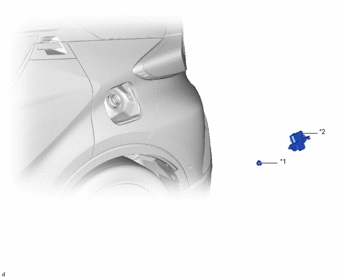
COMPONENTS
ILLUSTRATION
|
*1 |
FUEL FILLER OPENING LID LOCK RETAINER |
*2 |
FUEL LID LOCK WITH MOTOR ASSEMBLY |
Removal
REMOVAL
PROCEDURE
1. REMOVE DECK TRIM SIDE PANEL ASSEMBLY LH
Click here
.gif)
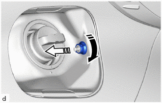
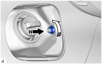
2. REMOVE FUEL FILLER OPENING LID LOCK RETAINER
(a) Remove the fuel filler opening lid lock retainer as shown in the illustration.
.png) |
Remove in this Direction (1) |
.png) |
Remove in this Direction (2) |
3. REMOVE FUEL LID LOCK WITH MOTOR ASSEMBLY
|
(a) Disengage the claws. |
|
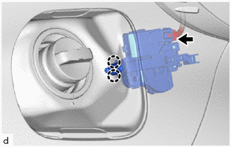
(b) Disconnect the connector to remove the fuel lid lock with motor assembly.
Inspection
INSPECTION
PROCEDURE
1. INSPECT FUEL LID LOCK WITH MOTOR ASSEMBLY
(a) Check the operation of the fuel lid lock with motor assembly (motor operation).
|
(1) Apply battery voltage to the fuel lid lock with motor assembly connector, and measure the shaft stroke. OK:
If the result is not as specified, replace the fuel lid lock with motor assembly. |
|
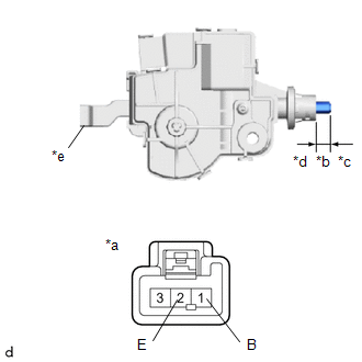
(b) Measure the shaft stroke.
OK:
|
Area |
Condition |
Specified Condition |
|---|---|---|
|
Shaft stroke |
Lever pulled |
16.05 mm (0.632 in.) |
If the result is not as specified, replace the fuel lid lock with motor assembly.
Installation
INSTALLATION
PROCEDURE
1. INSTALL FUEL LID LOCK WITH MOTOR ASSEMBLY
|
(a) Connect the connector. |
|
.png)
(b) Engage the claws to install the fuel lid lock with motor assembly.
2. INSTALL FUEL FILLER OPENING LID LOCK RETAINER
(a) Install the fuel filler opening lid lock retainer as shown in the illustration.
.png) |
Install in this Direction (1) |
.png) |
Install in this Direction (2) |
3. INSTALL DECK TRIM SIDE PANEL ASSEMBLY LH
Click here
.gif)
 Front Door Opening Trim Weatherstrip
Components
COMPONENTS
ILLUSTRATION
*1
COWL SIDE TRIM BOARD
*2
FRONT DOOR OPENING TRIM WEATHERSTRIP
*3
FRONT DOOR SCUFF PL ...

Other materials:
Toyota CH-R Service Manual > Rear Disc Brake Pad(for Tmc Made): Installation
INSTALLATION
CAUTION / NOTICE / HINT
NOTICE:
After replacing the rear disc brake pads, the brake pedal may feel soft due to
clearance between the rear disc brake pads and rear disc. Depress the brake pedal
several times until the brake pedal feels firm.
HINT:
The following procedure ...
Toyota CH-R Service Manual > Tire Pressure Warning System: ECU Power Source Circuit
DESCRIPTION
This is the power source for the tire pressure warning ECU and receiver.
WIRING DIAGRAM
CAUTION / NOTICE / HINT
NOTICE:
When replacing the tire pressure warning ECU and receiver, read the
transmitter IDs stored in the old ECU using the Techstream and write them
dow ...
Toyota C-HR (AX20) 2023-2026 Owner's Manual
Toyota CH-R Owners Manual
- For safety and security
- Instrument cluster
- Operation of each component
- Driving
- Interior features
- Maintenance and care
- When trouble arises
- Vehicle specifications
- For owners
Toyota CH-R Service Manual
- Introduction
- Maintenance
- Audio / Video
- Cellular Communication
- Navigation / Multi Info Display
- Park Assist / Monitoring
- Brake (front)
- Brake (rear)
- Brake Control / Dynamic Control Systems
- Brake System (other)
- Parking Brake
- Axle And Differential
- Drive Shaft / Propeller Shaft
- K114 Cvt
- 3zr-fae Battery / Charging
- Networking
- Power Distribution
- Power Assist Systems
- Steering Column
- Steering Gear / Linkage
- Alignment / Handling Diagnosis
- Front Suspension
- Rear Suspension
- Tire / Wheel
- Tire Pressure Monitoring
- Door / Hatch
- Exterior Panels / Trim
- Horn
- Lighting (ext)
- Mirror (ext)
- Window / Glass
- Wiper / Washer
- Door Lock
- Heating / Air Conditioning
- Interior Panels / Trim
- Lighting (int)
- Meter / Gauge / Display
- Mirror (int)
- Power Outlets (int)
- Pre-collision
- Seat
- Seat Belt
- Supplemental Restraint Systems
- Theft Deterrent / Keyless Entry

0.0072