Toyota CH-R Service Manual: Inspection
INSPECTION
PROCEDURE
1. INSPECT STEERING PAD SWITCH ASSEMBLY
(a) Measure the resistance according to the value(s) in the table below.
|
*A |
w/ Lane Departure Alert System |
*B |
w/ Voice Switch |
|
*C |
w/ Microphone |
- |
- |
|
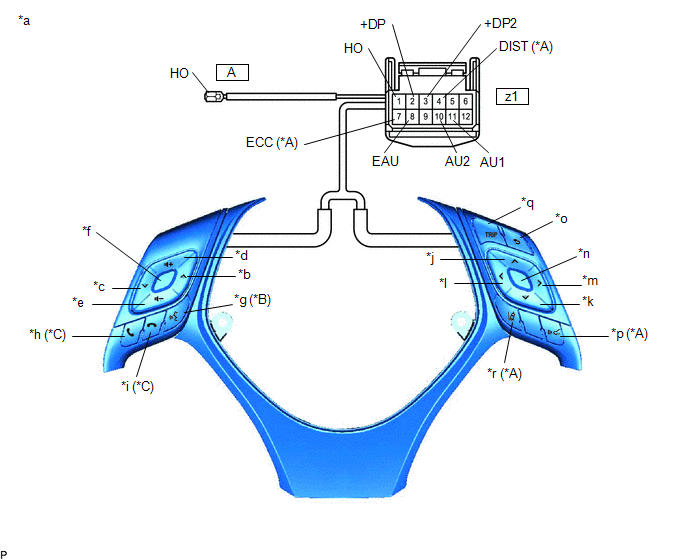
*a |
Component without harness connected (Steering Pad Switch Assembly) |
*b |
Seek+ |
|
*c |
Seek- |
*d |
Volume+ |
|
*e |
Volume- |
*f |
MODE |
|
*g |
Voice |
*h |
Off Hook |
|
*i |
On Hook |
*j |
Up |
|
*k |
Down |
*l |
Left |
|
*m |
Right |
*n |
Enter |
|
*o |
Back |
*p |
Distance Control |
|
*q |
TRIP |
*r |
Lane Departure Alert |
Standard Resistance:
|
Tester Connection |
Condition |
Specified Condition |
|---|---|---|
|
z1-11 (AU1) - z1-8 (EAU) |
No switch pushed |
95 to 105 kΩ |
|
Seek+ switch pushed |
Below 2.5 Ω |
|
|
Seek- switch pushed |
313 to 345 Ω |
|
|
Volume+ switch pushed |
950 to 1050 Ω |
|
|
Volume- switch pushed |
2955 to 3265 Ω |
|
|
z1-10 (AU2) - z1-8 (EAU) |
No switch pushed |
95 to 105 kΩ |
|
MODE switch pushed |
Below 2.5 Ω |
|
|
On hook switch pushed*1 |
313 to 345 Ω |
|
|
Off hook switch pushed*1 |
950 to 1050 Ω |
|
|
Voice switch pushed*2 |
2955 to 3265 Ω |
|
|
z1-3 (+DP2) - z1-8 (EAU) |
No switch pushed |
95 to 105 kΩ |
|
Left switch pushed |
Below 2.5 Ω |
|
|
Up switch pushed |
313 to 345 Ω |
|
|
Down switch pushed |
950 to 1050 Ω |
|
|
Right switch pushed |
2955 to 3265 Ω |
|
|
z1-2 (+DP) - z1-8 (EAU) |
No switch pushed |
95 to 105 kΩ |
|
Enter switch pushed |
Below 2.5 Ω |
|
|
TRIP switch pushed |
313 to 345 Ω |
|
|
Back switch pushed |
950 to 1050 Ω |
|
|
z1-4 (DIST) - z1-7 (ECC)*3 |
No switch pushed |
1 MΩ or higher |
|
Distance control switch pushed |
Below 2.5 Ω |
|
|
Lane departure alert switch pushed |
228 to 252 Ω |
|
|
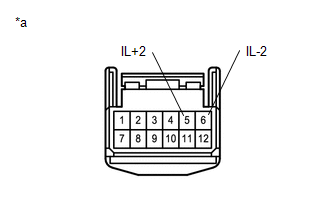
z1-1 (HO) - A-1(HO) |
Always |
Below 2.5 Ω |
- *1: w/ Microphone
- *2: w/ Voice Switch
- *3: w/ Lane Departure Alert System
If the result is not as specified, replace the steering pad switch assembly.
|
(b) Check that the illumination illuminates. (1) Apply battery voltage between the terminals of the switch, and check the illumination condition of the steering pad switch assembly. Standard:
If the result is not as specified, replace the steering pad switch assembly. |
|
 Removal
REMOVAL
CAUTION / NOTICE / HINT
The necessary procedures (adjustment, calibration, initialization, or registration)
that must be performed after parts are removed, installed, or replaced during th ...
 Installation
INSTALLATION
PROCEDURE
1. INSTALL STEERING PAD SWITCH ASSEMBLY
(a) Engage the 4 claws and 4 pins to install the steering pad switch assembly.
(b) Install the 2 screws.
(c) Connect connector to th ...
Other materials:
Toyota CH-R Service Manual > Smart Key System(for Start Function): Engine does not Start
DESCRIPTION
When the electrical key transmitter sub-assembly is in the cabin and the engine
switch is pressed, the certification ECU (smart key ECU assembly) receives a signal
and changes the power source mode. Additionally, when the shift lever is in P and
the brake pedal is depressed, the e ...
Toyota CH-R Service Manual > Continuously Variable Transaxle Assembly(when Using The Engine Support Bridge): Components
COMPONENTS
ILLUSTRATION
*1
NO. 1 ENGINE UNDER COVER
*2
REAR ENGINE UNDER COVER LH
*3
REAR ENGINE UNDER COVER RH
-
-
N*m (kgf*cm, ft.*lbf): Specified torque
-
...
Toyota C-HR (AX20) 2023-2026 Owner's Manual
Toyota CH-R Owners Manual
- For safety and security
- Instrument cluster
- Operation of each component
- Driving
- Interior features
- Maintenance and care
- When trouble arises
- Vehicle specifications
- For owners
Toyota CH-R Service Manual
- Introduction
- Maintenance
- Audio / Video
- Cellular Communication
- Navigation / Multi Info Display
- Park Assist / Monitoring
- Brake (front)
- Brake (rear)
- Brake Control / Dynamic Control Systems
- Brake System (other)
- Parking Brake
- Axle And Differential
- Drive Shaft / Propeller Shaft
- K114 Cvt
- 3zr-fae Battery / Charging
- Networking
- Power Distribution
- Power Assist Systems
- Steering Column
- Steering Gear / Linkage
- Alignment / Handling Diagnosis
- Front Suspension
- Rear Suspension
- Tire / Wheel
- Tire Pressure Monitoring
- Door / Hatch
- Exterior Panels / Trim
- Horn
- Lighting (ext)
- Mirror (ext)
- Window / Glass
- Wiper / Washer
- Door Lock
- Heating / Air Conditioning
- Interior Panels / Trim
- Lighting (int)
- Meter / Gauge / Display
- Mirror (int)
- Power Outlets (int)
- Pre-collision
- Seat
- Seat Belt
- Supplemental Restraint Systems
- Theft Deterrent / Keyless Entry

0.0065