Toyota CH-R Service Manual: Short to GND or Open in Buzzer (C1ABE)
DESCRIPTION
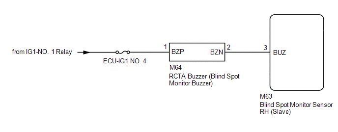
- DTC C1ABE is stored when the blind spot monitor sensor RH (Slave) detects a short to ground or open in the RCTA buzzer (blind spot monitor buzzer) circuit.
|
DTC No. |
Detection Item |
DTC Detection Condition |
Trouble Area |
|---|---|---|---|
|
C1ABE |
Short to GND or Open in Buzzer |
Both of the following conditions are met:
|
|
WIRING DIAGRAM
CAUTION / NOTICE / HINT
NOTICE:
- When checking for DTCs, make sure that the blind spot monitor system is turned on.
- Inspect the fuses for circuits related to this system before performing the following procedure.
PROCEDURE
|
1. |
CHECK DTC |
(a) Turn the ignition switch off.
(b) Turn the ignition switch to ON.
(c) Recheck for DTCs and check if the same DTC is output again.
Body Electrical > Blind Spot Monitor Slave > Trouble CodesOK:
No DTCs are output.
| OK | .gif) |
USE SIMULATION METHOD TO CHECK
|
|
.gif)
|
2. |
CHECK HARNESS AND CONNECTOR (RCTA BUZZER - BATTERY AND BLIND SPOT MONITOR SENSOR RH (SLAVE)) |
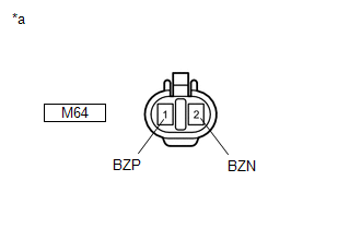
(a) Disconnect the M64 RCTA buzzer (blind spot monitor buzzer) connector.
(b) Disconnect the M63 blind spot monitor sensor RH (Slave) connector.
(c) Measure the resistance according to the value(s) in the table below.
Standard Resistance:
|
Tester Connection |
Condition |
Specified Condition |
|---|---|---|
|
M64-2 (BZN) - M63-3 (BUZ) |
Always |
Below 1 Ω |
|
M64-2 (BZN) - Body ground |
Always |
10 kΩ or higher |
|
(d) Measure the voltage according to the value(s) in the table below. Standard Voltage:
|
|
| NG | |
REPAIR OR REPLACE HARNESS OR CONNECTOR |
|
|
3. |
REPLACE RCTA BUZZER (BLIND SPOT MONITOR BUZZER) |
(a) Replace the RCTA buzzer (blind spot monitor buzzer).
Click here
.gif)
|
|
4. |
CHECK DTC |
(a) Clear the DTCs.
Click here
(b) Recheck for DTCs and check if the same DTC is output again.
Body Electrical > Blind Spot Monitor Slave > Trouble CodesOK:
No DTCs are output.
| OK | |
END |
| NG | |
REPLACE BLIND SPOT MONITOR SENSOR RH (SLAVE) |
 Software Incompatibility with Body Control Module "B" (U1331)
DESCRIPTION
This DTC is stored when the destination information of the main body ECU (multiplex
network body ECU) does not match that of the blind spot monitor sensors.
DTC No.
...
 Blind Spot Monitor Slave Module Beam Axis Inspection Incomplete (C1ABC)
DESCRIPTION
This DTC is stored when a beam axis adjustment has not been performed for the
blind spot monitor sensor RH (Slave).
HINT:
This DTC is always stored after replacing a blind spot monito ...
Other materials:
Toyota CH-R Service Manual > Occupant Classification System: Parts Location
PARTS LOCATION
ILLUSTRATION
*1
FRONT SEAT INNER BELT ASSEMBLY RH
*2
AIRBAG SENSOR ASSEMBLY
*3
OCCUPANT DETECTION ECU
*4
FRONT IN WEIGHT DETECTION SENSOR SUB-ASSEMBLY
*5
REAR ...
Toyota CH-R Service Manual > Door Control Transmitter(w/ Smart Key System): Removal
REMOVAL
CAUTION / NOTICE / HINT
NOTICE:
Take extra care when handling these precision electronic components.
PROCEDURE
1. REMOVE TRANSMITTER BATTERY
(a) Slide the release hook knob to remove the mechanical key as shown in the
illustration.
*a
Hook Knob
...
Toyota C-HR (AX20) 2023-2026 Owner's Manual
Toyota CH-R Owners Manual
- For safety and security
- Instrument cluster
- Operation of each component
- Driving
- Interior features
- Maintenance and care
- When trouble arises
- Vehicle specifications
- For owners
Toyota CH-R Service Manual
- Introduction
- Maintenance
- Audio / Video
- Cellular Communication
- Navigation / Multi Info Display
- Park Assist / Monitoring
- Brake (front)
- Brake (rear)
- Brake Control / Dynamic Control Systems
- Brake System (other)
- Parking Brake
- Axle And Differential
- Drive Shaft / Propeller Shaft
- K114 Cvt
- 3zr-fae Battery / Charging
- Networking
- Power Distribution
- Power Assist Systems
- Steering Column
- Steering Gear / Linkage
- Alignment / Handling Diagnosis
- Front Suspension
- Rear Suspension
- Tire / Wheel
- Tire Pressure Monitoring
- Door / Hatch
- Exterior Panels / Trim
- Horn
- Lighting (ext)
- Mirror (ext)
- Window / Glass
- Wiper / Washer
- Door Lock
- Heating / Air Conditioning
- Interior Panels / Trim
- Lighting (int)
- Meter / Gauge / Display
- Mirror (int)
- Power Outlets (int)
- Pre-collision
- Seat
- Seat Belt
- Supplemental Restraint Systems
- Theft Deterrent / Keyless Entry

0.0074