Toyota CH-R Service Manual: Data List / Active Test
DATA LIST / ACTIVE TEST
READ DATA LIST
HINT:
Using the Techstream to read the Data List allows the values or states of switches, sensors, actuators and other items to be read without removing any parts. This non-intrusive inspection can be very useful because intermittent conditions or signals may be discovered before parts or wiring is disturbed. Reading the Data List information early in troubleshooting is one way to save diagnostic time.
NOTICE:
In the table below, the values listed under "Normal Condition" are reference values. Do not depend solely on these reference values when deciding whether a part is faulty or not.
(a) Turn the engine switch off.
(b) Connect the Techstream to the DLC3.
(c) Turn the engine switch on (IG).
(d) Turn the Techstream on.
(e) Enter the following menus: Body Electrical / (desired system) / Data List.
(f) Read the Data List according to the display on the Techstream.
(g) Using the Techstream, confirm the Data List items to help determine the cause of the problem.
NOTICE:
- The steering lock ECU (steering lock actuator or upper bracket assembly) communicates with the Techstream through the certification ECU (smart key ECU assembly) which uses CAN communication. If the CAN communication system or certification ECU (smart key ECU assembly) is malfunctioning, Data List items may not be normal.
- When using the Techstream with the engine switch off, connect the Techstream to the vehicle and turn a courtesy light switch on and off at intervals of 1.5 seconds or less until communication between the Techstream and the vehicle begins. Then select the vehicle type under manual mode and enter the following menus: Body Electrical / Smart Key. While using the Techstream, periodically turn a courtesy light switch on and off at intervals of 1.5 seconds or less to maintain communication between the Techstream and the vehicle.
|
Tester Display |
Measurement Item |
Range |
Normal Condition |
Diagnostic Note |
|---|---|---|---|---|
|
Shift P Signal |
Shift position (P) signal |
ON or OFF |
ON: Shift lever in P OFF: Shift lever not in P |
|
|
Steering Unlock Switch |
State of steering unlock sensor signal output from steering lock ECU (steering lock actuator or upper bracket assembly) |
ON or OFF |
ON: Steering unlocked OFF: Steering locked |
This item can be used to determine the cause of problems when the steering does not lock or unlock. HINT:
|
|
Str Lock/Unlock Wait T-Out |
Steering lock or unlock malfunction |
Yes or No |
Yes: Steering lock/unlock timed out (Lock bar stuck, etc.) No: Steering locks/unlocks normally within specified time |
The engine cannot be started when this item is "Yes". |
|
Tester Display |
Measurement Item |
Range |
Normal Condition |
Diagnostic Note |
|---|---|---|---|---|
|
# Codes |
Number of DTCs |
Min: 0 Max: 255 |
Number of stored DTCs displayed |
- |
|
Immobiliser |
State of immobiliser system determined by certification ECU (smart key ECU assembly) |
Set or Unset |
Set: Immobiliser set (engine start prohibited) (engine switch off) Unset: Immobiliser unset (engine start permitted) (engine switch on (ACC) or on (IG)) |
HINT:
|
|
Steering Lock Sleep Cond |
Steering lock ECU (steering lock actuator or upper bracket assembly) sleep availability |
Yes or No |
Yes: Sleep available No: Sleep not available |
- |
|
Steering Lock Start Cond |
Steering lock ECU (steering lock actuator or upper bracket assembly) wake up signal status |
Yes or No |
Yes: Wake up signal sent No: Wake up signal not sent |
- |
|
Engine Start Condition |
State of engine start permission signal determined by steering lock ECU (steering lock actuator or upper bracket assembly) sent to certification ECU (smart key ECU assembly) |
OK or NG |
OK: Engine start permitted NG: Engine start prohibited |
|
|
Sensor Value |
Record of malfunction of lock or unlock sensor in steering lock ECU (steering lock actuator or upper bracket assembly) (DTC B2781 is output) |
OK or NG(Past) |
OK: No record of lock/unlock sensor malfunction in steering lock ECU (steering lock actuator or upper bracket assembly) NG(Past): Record of lock/unlock sensor in steering lock ECU (steering lock actuator or upper bracket assembly) turning ON at same time exists |
When this item displays "NG", the sensor inside the steering lock ECU (steering lock actuator or upper bracket assembly) may be malfunctioning, or there may be a mechanical malfunction. |
|
Power Supply Short |
Record of malfunction of signal sent to steering lock motor (steering lock actuator or upper bracket assembly) from certification ECU (smart key ECU assembly) (short circuit) (DTC B2782 is output) |
OK or NG(Past) |
OK: No record of malfunction (short circuit) NG(Past): Record of malfunction (short circuit) exists |
This item records malfunctions in the circuit between the certification ECU (smart key ECU assembly) and steering lock motor (steering lock actuator or upper bracket assembly). |
|
Motor Driver Short |
Record of malfunction of motor activation circuit in steering lock ECU (steering lock actuator or upper bracket assembly) (short circuit) (DTC B2781 is output) |
OK or NG(Past) |
OK: No record of malfunction (short circuit) NG(Past): Record of malfunction (short circuit) exists |
This item records malfunctions in the motor activation circuit inside the steering lock ECU (steering lock actuator or upper bracket assembly) (short circuit). |
|
Lock/Unlock Receive |
Reception state of steering lock or unlock request signal from certification ECU (smart key ECU assembly) |
Yes or No |
Yes: Record of receiving lock or unlock request signal exists No: No record of receiving lock or unlock request signal |
- |
|
Lock Bar Stuck Error |
Record of lock bar not properly unlocking after being commanded to unlock for certain amount of time |
OK or NG(Past) |
OK: No record of stuck lock bar NG(Past): Record of stuck lock bar exists |
- |
|
Engine Start Request |
Reception state of engine start permission signal determined by steering lock ECU (steering lock actuator or upper bracket assembly) sent to certification ECU (smart key ECU assembly) |
OK or NG |
OK: Receiving signal NG: Not receiving signal |
|
|
S Code Check |
Verification result between certification ECU (smart key ECU assembly) and ID code box (immobiliser code ECU) |
OK or NG |
OK: Verification result normal NG: Verification result abnormal |
When a malfunction is present:
|
|
L Code Check |
Verification result between ID code box (immobiliser code ECU) and steering lock ECU (steering lock actuator or upper bracket assembly) |
OK or NG |
OK: Verification result normal NG: Verification result abnormal |
When a malfunction is present:
|
|
Unlock Request Receive |
Reception state of steering unlock request signal by certification ECU (smart key ECU assembly) sent to ID code box (immobiliser code ECU) HINT:
|
OK or NG |
OK: Unlock request received within 10 seconds of turning engine switch on (IG) or on (ACC) or starting engine NG: Except above |
|
|
Lock Request Receive |
Reception state of steering lock request signal by certification ECU (smart key ECU assembly) sent to ID code box (immobiliser code ECU) HINT:
|
OK or NG |
OK: Lock request received within 10 seconds of opening any door with engine switch off and shift lever in P NG: Except above |
If this item does not change to "OK" even though the steering lock conditions are met, the certification ECU (smart key ECU assembly) may be malfunctioning. |
|
S Code Check(Past) |
Verification result between certification ECU (smart key ECU assembly) and ID code box (immobiliser code ECU) (Past) |
OK or NG(Past) |
OK: Verification result normal NG(Past): Verification result abnormal (Past) |
- |
|
L Code Check(Past) |
Verification result between ID code box (immobiliser code ECU) and steering lock ECU (steering lock actuator or upper bracket assembly) (Past) |
OK or NG(Past) |
OK: Verification result normal NG(Past): Verification result abnormal (Past) |
- |
|
Steering Lock |
State of whether steering lock ECU (steering lock actuator or upper bracket assembly) determined steering is locked |
Set or Unset |
Set: Steering locked Unset: Steering unlocked |
If this item displays "Unset", the steering is not locked. |
|
Steering Unlock |
State of whether steering lock ECU (steering lock actuator or upper bracket assembly) determined steering is unlocked |
Set or Unset |
Set: Steering unlocked Unset: Steering locked |
If this item displays "Unset", the steering is not unlocked (engine cannot be started). |
|
Engine Start Indicator |
Smart warning light |
ON or OFF |
Customize setting displayed |
- |
|
Open in IG2 |
History of IG2 input of the steering lock ECU (steering lock actuator or upper bracket assembly) |
OK or NG(Past) |
OK: History of open in IG2 exists NG(Past): No history of open in IG2 exists |
If this item displays "OK", the steering lock ECU (steering lock actuator or upper bracket assembly) has an IG2 input circuit malfunction. |
HINT:
Unlock operation conditions for the steering lock:
When the following condition is met, the unlock operation is performed:
The engine switch is on (ACC) or on (IG).
- When the engine switch is turned on (ACC) or on (IG) and the key and certification ECU (smart key ECU assembly) are verified, the steering is unlocked.
When any of the following conditions are met, key verification is performed.
- The brake pedal is depressed so that the engine can be started.
- 30 seconds have elapsed after opening and closing a door.
- The engine switch is pressed.
Key verification occurs when the code emitted from the key and the code stored in the certification ECU (smart key ECU assembly) are compared to check that they match.
Certification ECU (smart key ECU assembly) verification occurs when the S code and L code are verified while the engine is being started or the engine switch is being pushed. The ID code box (immobiliser code ECU) uses the S code to determine whether the certification ECU (smart key ECU assembly) is authorized. The steering lock ECU (steering lock actuator or upper bracket assembly) uses the L code to determine whether the ID code box (immobiliser code ECU) is authorized.
Lock operation conditions for the steering:
When the following conditions are met and the certification ECU (smart key ECU assembly) has been verified, the lock operation is performed.
- The engine switch is off.
- The shift lever is in P.
- A door is opened or a door lock operation (door lock, wireless door lock or key-linked lock) is performed.
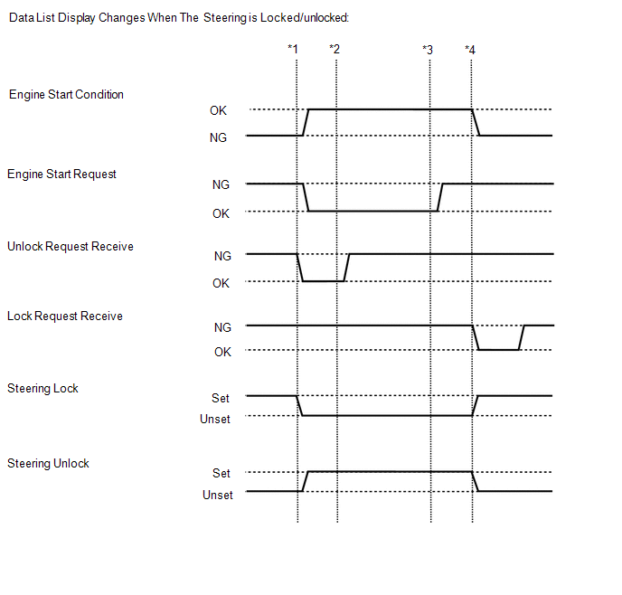
HINT:
The following example shows the behavior of various Data List items when the shift lever is in P, the brake pedal is not depressed, the vehicle is normal and the power source mode changes.
 Get into the vehicle while carrying
the key. With the engine switch off, the shift lever in P and all the doors closed,
perform the following procedures and check the power source mode.
Get into the vehicle while carrying
the key. With the engine switch off, the shift lever in P and all the doors closed,
perform the following procedures and check the power source mode.
HINT:
*1: Without depressing the brake pedal, press the engine switch and check that the power source mode changes to on (ACC).
*2: Without depressing the brake pedal, press the engine switch and check that the power source mode changes to on (IG).
*3: Press the engine switch and check that the power source mode changes to off.
*4: Release the brake pedal, open the driver door and check that the steering locks.
Body Electrical > Main Body > Data List|
Tester Display |
Measurement Item |
Range |
Normal Condition |
Diagnostic Note |
|---|---|---|---|---|
|
FL Door Courtesy SW |
Front door courtesy light switch assembly LH |
ON or OFF |
ON: Front door LH open OFF: Front door LH closed |
If this item does not change according to the actual state of the driver door, there is a malfunction in the door courtesy light switch or related part. |
ACTIVE TEST
HINT:
Using the Techstream to perform Active Tests allows relays, VSVs, actuators and other items to be operated without removing any parts. This non-intrusive functional inspection can be very useful because intermittent operation may be discovered before parts or wiring is disturbed. Performing Active Tests early in troubleshooting is one way to save diagnostic time. Data List information can be displayed while performing Active Tests.
(a) Turn the engine switch off.
(b) Connect the Techstream to the DLC3.
(c) Turn the engine switch on (IG).
(d) Turn the Techstream on.
(e) Enter the following menus: Body Electrical / (desired system) / Active Test.
(f) According to the display on the Techstream, perform the Active Test.
Body Electrical > Power Source Control > Active Test|
Tester Display |
Measurement Item |
Control Range |
Diagnostic Note |
|---|---|---|---|
|
P Supply for Steering Lock |
Certification ECU (smart key ECU assembly) |
OFF/ON HINT: OFF: Power is not supplied ON: Power is supplied |
When performing this Active Test, make sure the following condition is met: The engine switch is on (IG). |
 Dtc Check / Clear
DTC CHECK / CLEAR
NOTICE:
The steering lock ECU (steering lock actuator or upper bracket assembly)
does not store history DTCs. If any DTCs are output, confirm and record
them as soo ...
 Diagnostic Trouble Code Chart
DIAGNOSTIC TROUBLE CODE CHART
Steering Lock System
DTC No.
Detection Item
DTC Detection Condition
Note
Link
B2781
O ...
Other materials:
Toyota CH-R Service Manual > Rear Door Outside Moulding: Components
COMPONENTS
ILLUSTRATION
*1
REAR DOOR OUTSIDE MOULDING
*2
HOLE COVER
*3
GASKET
-
-
ILLUSTRATION
*1
NO. 2 OUTSIDE MOULDING RETAINER
*2
REAR DOOR UP ...
Toyota CH-R Service Manual > Navigation System: Data Signal Circuit between Radio Receiver and Stereo Jack Adapter
DESCRIPTION
The No. 1 stereo jack adapter assembly sends the sound data signal or image data
signal from a USB device to the radio and display receiver assembly via this circuit.
WIRING DIAGRAM
PROCEDURE
1.
CHECK HARNESS AND CONNECTOR (RADIO AND DISPLAY RECEIVER ASSEMB ...
Toyota C-HR (AX20) 2023-2026 Owner's Manual
Toyota CH-R Owners Manual
- For safety and security
- Instrument cluster
- Operation of each component
- Driving
- Interior features
- Maintenance and care
- When trouble arises
- Vehicle specifications
- For owners
Toyota CH-R Service Manual
- Introduction
- Maintenance
- Audio / Video
- Cellular Communication
- Navigation / Multi Info Display
- Park Assist / Monitoring
- Brake (front)
- Brake (rear)
- Brake Control / Dynamic Control Systems
- Brake System (other)
- Parking Brake
- Axle And Differential
- Drive Shaft / Propeller Shaft
- K114 Cvt
- 3zr-fae Battery / Charging
- Networking
- Power Distribution
- Power Assist Systems
- Steering Column
- Steering Gear / Linkage
- Alignment / Handling Diagnosis
- Front Suspension
- Rear Suspension
- Tire / Wheel
- Tire Pressure Monitoring
- Door / Hatch
- Exterior Panels / Trim
- Horn
- Lighting (ext)
- Mirror (ext)
- Window / Glass
- Wiper / Washer
- Door Lock
- Heating / Air Conditioning
- Interior Panels / Trim
- Lighting (int)
- Meter / Gauge / Display
- Mirror (int)
- Power Outlets (int)
- Pre-collision
- Seat
- Seat Belt
- Supplemental Restraint Systems
- Theft Deterrent / Keyless Entry

0.0077