Toyota CH-R Service Manual: Terminals Of Ecu
TERMINALS OF ECU
CHECK CERTIFICATION ECU (SMART KEY ECU ASSEMBLY)
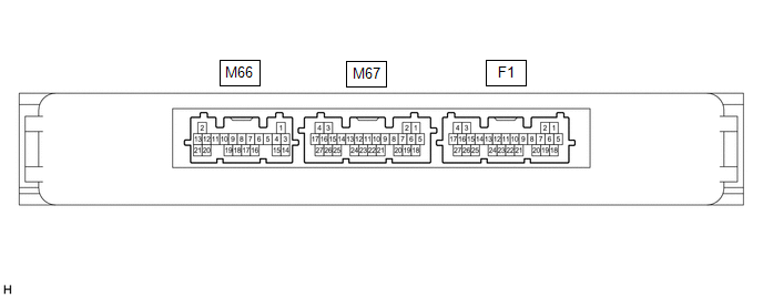
(a) Disconnect the M66, M67 and F1 certification ECU (smart key ECU assembly) connectors.
(b) Measure the voltage and resistance according to the value(s) in the table below.
HINT:
Measure the values on the wire harness side with the connector disconnected.
|
Tester Connection |
Input/Output |
Wiring Color |
Terminal Description |
Condition |
Specified Condition |
Related Data List Item |
|---|---|---|---|---|---|---|
|
M66-20 (STA) - Body ground |
Input |
LG - Body ground |
When starting the engine, this monitors the voltage sent from terminal STAR to the starter relay to judge whether the engine is "being started". |
20°C (68°F) |
101.69 to 153.85 Ω |
- |
|
M66-9 (STAR) - Body ground |
Input/Output |
W - Body ground |
Outputs voltage to the starter relay
HINT: When Hi is selected, a start request signal (STAR) will not be output even though a start request signal (STSW) is input. |
Shift lever in any position other than P or N → Shift lever in P or N (at 20°C (68°F)) |
10 kΩ or higher → 101.69 to 153.85 Ω |
- |
|
Receives neutral start switch (P, N position detection) signal
|
Perform the following operations except while the engine is cranking:
|
30 kΩ or higher → 101.69 to 153.85 Ω |
Neutral SW/ Clutch SW |
|||
|
M66-16 (NE) - Body ground |
Input |
GR - Body ground |
Engine speed signal |
Always |
10 kΩ or higher |
Engine Condition |
|
M67-25 (STP1) - Body ground |
Input |
BE - Body ground |
Stop light switch signal |
Brake pedal depressed → Brake pedal released |
9 V or higher → 1 V or less |
Stop Light |
|
F1-4 (+B) - F1-18 (E) |
Input |
L - W-B |
Power source |
Always |
11 to 14 V |
- |
|
F1-22 (P) - F1-18 (E) |
Input |
L - W-B |
P position signal |
Shift lever in P → Shift lever not in P |
30 kΩ or higher → Below 200 Ω |
Shift P Signal |
|
F1-18 (E) - Body ground |
- |
W-B - Body ground |
GND |
Always |
Below 1 Ω |
- |
|
F1-21 (SSW2) - Body ground |
Input |
GR - Body ground |
SSW2 contact signal HINT: Backup for SSW1. Behaves the same way as SSW1. |
Engine switch pushed → Engine switch not pushed |
Below 15 Ω → 10 kΩ or higher |
Start Switch2 |
|
F1-23 (SSW1) - Body ground |
Input |
W - Body ground |
SSW1 contact signal |
Engine switch pushed → Engine switch not pushed |
Below 15 Ω → 10 kΩ or higher |
Start Switch1 |
|
F1-16 (ACCD) - Body ground |
Output |
LG - Body ground |
ACC signal |
20°C (68°F) |
285.71 to 428.57 Ω |
ACC Relay Monitor |
|
F1-17 (IG1D) - Body ground |
Output |
GR - Body ground |
IG signal |
20°C (68°F) |
60.78 to 89.11 Ω |
IG Relay Monitor (Outside) |
|
F1-19 (SPD) - Body ground |
Input |
V - Body ground |
Vehicle speed signal |
Always |
30 kΩ or higher |
Vehicle Speed Signal |
(c) Reconnect the M66, M67 and F1 certification ECU (smart key ECU assembly) connectors.
(d) Measure the voltage and check for pulses according to the value(s) in the table below.
|
Tester Connection |
Input/Output |
Wiring Color |
Terminal Description |
Condition |
Specified Condition |
Related Data List Item |
|---|---|---|---|---|---|---|
|
M66-20 (STA) - F1-18 (E) |
Input |
LG - W-B |
When starting the engine, this monitors the voltage sent from terminal STAR to the starter relay to judge whether the engine is "being started". |
Engine switch pressed and held with brake pedal depressed (starter on) → Approximately 1 second after engine switch released (starter off) |
6 V or higher*1 → 1.0 V or less |
- |
|
M66-9 (STAR) - F1-18 (E) |
Input/Output |
W - W-B |
Outputs voltage to the starter relay
HINT: When Hi is selected, a start request signal (STAR) will not be output even though a start request signal (STSW) is input. |
Engine switch pressed and held with brake pedal depressed (starter on) → Approximately 1 second after engine switch released (starter off) |
6 V or higher*1 → 1.0 V or less |
- |
|
Receives neutral start switch (P, N position detection) signal
|
Perform the following operations except while the engine is cranking:
|
9 V or higher → 2.7 V or less |
Neutral SW/ Clutch SW |
|||
|
M66-16 (NE) - F1-18 (E) |
Input |
GR - W-B |
Engine speed signal |
Idling (engine warmed up) |
Pulse generation (See waveform 1) |
Engine Condition |
|
M67-25 (STP1) - F1-18 (E) |
Input |
BE - W-B |
Stop light switch signal |
Brake pedal released → Brake pedal depressed |
1 V or less → 9 V or higher |
Stop Light Switch1 |
|
F1-14 (SLP) - F1-18 (E) |
Input |
G - W-B |
Steering lock position signal |
Steering locked → Steering unlocked |
11 to 14 V → 1.5 V or less |
Steering Unlock Switch |
|
F1-25 (SLR+) - F1-18 (E) |
Output |
P - W-B |
Steering lock motor operation command signal (Steering lock motor operation permission signal sent from the certification ECU (smart key ECU assembly)) |
When a door is opened, the steering lock motor will be operated if all of the following conditions are met:
|
Pulse generation (See waveform 2) |
- |
|
F1-22 (P) - F1-18 (E) |
Input |
L - W-B |
P position signal |
Shift lever in P → Shift lever not in P |
9 V or higher → 2.76 V or less |
Shift P Signal |
|
F1-21 (SSW2) - F1-18 (E) |
Input |
GR - W-B |
SSW2 contact signal HINT: Backup for SSW1. Behaves the same way as SSW1. |
Engine switch not pushed → Engine switch pushed |
9 V or higher → 1 V or less |
Start Switch2 |
|
F1-23 (SSW1) - F1-18 (E) |
Input |
W - W-B |
SSW1 contact signal |
Engine switch not pushed → Engine switch pushed |
9 V or higher → 1 V or less |
Start Switch1 |
|
F1-16 (ACCD) - F1-18 (E) |
Output |
LG - W-B |
ACC signal |
Engine switch off → Engine switch on (ACC) |
1 V or less → 8.5 V or higher |
ACC Relay Monitor |
|
F1-17 (IG1D) - F1-18 (E) |
Output |
GR - W-B |
IG signal |
Engine switch on (ACC) → Engine switch on (IG) |
1 V or less → 9 V or higher |
IG Relay Monitor (Outside) |
|
F1-19 (SPD) - F1-18 (E) |
Input |
V - W-B |
Vehicle speed signal |
Vehicle being driven at approx. 5 km/h (3 mph) |
Pulse generation (See waveform 3) |
Vehicle Speed Signal |
|
F1-8 (CLG5) - F1-18 (E) |
Output |
SB - W-B |
Output to No. 1 indoor electrical key antenna assembly (front floor) |
Procedure:
|
Pulse generation (See waveform 4) |
Overhead + Front Room (key diagnostic mode) |
|
F1-9 (CG5B) - F1-18 (E) |
Output |
R - W-B |
Output to No. 1 indoor electrical key antenna assembly (front floor) (terminal on opposite side of component from CLG5 output terminal) |
Procedure:
|
Pulse generation (See waveform 4) |
Overhead + Front Room (key diagnostic mode) |
|
M67-11 (CLG7) - F1-18 (E) |
Output |
B - W-B |
Output to No. 3 indoor electrical key antenna assembly (inside luggage compartment) |
Procedure:
|
Pulse generation (See waveform 4) |
Overhead + Back Door (inside) (key diagnostic mode) |
|
M67-10 (CG7B) - F1-18 (E) |
Output |
W - W-B |
Output to No. 3 indoor electrical key antenna assembly (inside luggage compartment) (terminal on opposite side of component from CLG7 output terminal) |
Procedure:
|
Pulse generation (See waveform 4) |
Overhead + Back Door (inside) (key diagnostic mode) |
HINT:
- *1: While the engine is cranking, the battery voltage may drop to approximately 6 V.
- The waveform of the steering lock actuator motor stopped can be checked without performing any particular operation.
- The waveform of the steering lock actuator motor operating can be checked
if either of the following operations is performed:
- To unlock the steering, bring the electrical key transmitter sub-assembly into the cabin and turn the engine switch on (ACC) or on (IG).
- To lock the steering, open a door with the engine switch off and the shift lever in P.
(e) Using an oscilloscope, check the waveform of the ECU.
NOTICE:
The oscilloscope waveform shown in the illustration is an example for reference only. Noise, chattering, etc. are not shown.
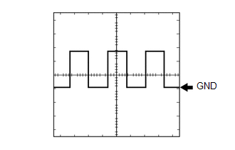
(1) Waveform 1

|
Item |
Content |
|---|---|
|
Tester Connection |
M66-16 (NE) - F1-18 (E) |
|
Tool Setting |
2 V/DIV., 2 ms./DIV. |
|
Condition |
Idling (engine warmed up) |
HINT:
The wavelength becomes shorter as the engine speed increases.
(2) Waveform 2
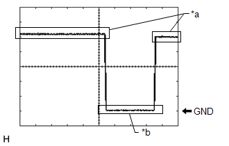
|
*a |
Steering lock motor not operating |
|
*b |
Steering lock motor operating |
|
Item |
Content |
|---|---|
|
Tester Connection |
F1-25 (SLR+) - F1-18 (E) |
|
Tool Setting |
2 V/DIV., 200 ms./DIV. |
|
Condition |
Steering lock motor stopped → Steering lock motor operating → Steering lock motor stopped |
(3) Waveform 3
|
Item |
Content |
|---|---|
|
Tester Connection |
F1-19 (SPD) - F1-18 (E) |
|
Tool Setting |
5 V/DIV., 20 ms./DIV. |
|
Condition |
Vehicle being driven at approx. 5 km/h (3 mph) |
HINT:
The wavelength becomes shorter as the vehicle speed increases.
(4) Waveform 4
.png)
|
*a |
For 30 seconds after any door closed |
|
*b |
After 30 seconds or more have elapsed since any door closed |
|
Item |
Content |
|---|---|
|
Tester Connection |
F1-8 (CLG5) - F1-18 (E) F1-9 (CG5B) - F1-18 (E) M67-11 (CLG7) - F1-18 (E) M67-10 (CG7B) - F1-18 (E) |
|
Tool Setting |
2 V/DIV., 500 ms/DIV. |
|
Condition |
Procedure:
|
CHECK STEERING LOCK ECU (STEERING LOCK ACTUATOR OR UPPER BRACKET ASSEMBLY)
Click here .gif)
CHECK ID CODE BOX (IMMOBILISER CODE ECU)
Click here
CHECK ECM
Click here
CHECK ENGINE SWITCH
Click here
 Diagnosis System
DIAGNOSIS SYSTEM
DESCRIPTION
(a) Smart key system (for Start Function) data and Diagnostic Trouble Codes (DTCs)
can be read through the Data Link Connector 3 (DLC3) of the vehicle. When the system ...
 Dtc Check / Clear
DTC CHECK / CLEAR
NOTICE:
When using the Techstream with the engine switch off, connect the Techstream
to the DLC3 and turn a courtesy light switch on and off at intervals of 1.5 seconds
or less ...
Other materials:
Toyota CH-R Service Manual > Front Seat Inner Belt Assembly: Components
COMPONENTS
ILLUSTRATION
*A
for Driver Side
*B
for Front Passenger Side
*1
FRONT SEAT INNER BELT ASSEMBLY
*2
FRONT SEAT BELT ANCHOR PLATE
Tightening torque for "Major areas ...
Toyota CH-R Service Manual > Door / Hatch: Front Door Opening Trim Weatherstrip
Components
COMPONENTS
ILLUSTRATION
*1
COWL SIDE TRIM BOARD
*2
FRONT DOOR OPENING TRIM WEATHERSTRIP
*3
FRONT DOOR SCUFF PLATE
-
-
Removal
REMOVAL
CAUTION / NOTICE / HINT
HINT:
...
Toyota C-HR (AX20) 2023-2026 Owner's Manual
Toyota CH-R Owners Manual
- For safety and security
- Instrument cluster
- Operation of each component
- Driving
- Interior features
- Maintenance and care
- When trouble arises
- Vehicle specifications
- For owners
Toyota CH-R Service Manual
- Introduction
- Maintenance
- Audio / Video
- Cellular Communication
- Navigation / Multi Info Display
- Park Assist / Monitoring
- Brake (front)
- Brake (rear)
- Brake Control / Dynamic Control Systems
- Brake System (other)
- Parking Brake
- Axle And Differential
- Drive Shaft / Propeller Shaft
- K114 Cvt
- 3zr-fae Battery / Charging
- Networking
- Power Distribution
- Power Assist Systems
- Steering Column
- Steering Gear / Linkage
- Alignment / Handling Diagnosis
- Front Suspension
- Rear Suspension
- Tire / Wheel
- Tire Pressure Monitoring
- Door / Hatch
- Exterior Panels / Trim
- Horn
- Lighting (ext)
- Mirror (ext)
- Window / Glass
- Wiper / Washer
- Door Lock
- Heating / Air Conditioning
- Interior Panels / Trim
- Lighting (int)
- Meter / Gauge / Display
- Mirror (int)
- Power Outlets (int)
- Pre-collision
- Seat
- Seat Belt
- Supplemental Restraint Systems
- Theft Deterrent / Keyless Entry

0.0073