Toyota CH-R Service Manual: Removal
REMOVAL
CAUTION / NOTICE / HINT
The necessary procedures (adjustment, calibration, initialization, or registration) that must be performed after parts are removed, installed, or replaced during the seat position airbag sensor removal/installation are shown below.
Necessary Procedure After Parts Removed/Installed/Replaced|
Replacement Part or Procedure |
Necessary Procedures |
Effects/Inoperative when not performed |
Link |
|---|---|---|---|
|
Disconnect cable from negative battery terminal |
Memorize steering angle neutral point |
Lane departure alert system (w/ Steering Control) |
|
|
Pre-collision system |
|||
|
Initialize back door lock |
Power door lock control system |
|
PROCEDURE
1. REMOVE FRONT SEAT ASSEMBLY
Click here .gif)
2. REMOVE SEAT SLIDE POSITION SENSOR PROTECTOR
|
(a) Disengage the clamp and disconnect the connector. |
|
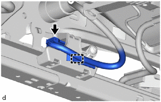
(b) Pull the seat slide position sensor protector in the direction indicated by the arrow (1), to disengage the pin, and then slide the seat slide position sensor protector in the direction indicated by the arrows (2) shown in the illustration to remove it.
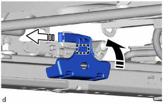
.png) |
Remove in this Direction (1) |
.png) |
Remove in this Direction (2) |
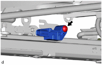
3. REMOVE SEAT POSITION AIRBAG SENSOR
|
(a) Using a T30 "TORX" socket wrench, remove the bolt and seat position airbag sensor. |
|
 On-vehicle Inspection
ON-VEHICLE INSPECTION
CAUTION / NOTICE / HINT
CAUTION:
Be sure to correctly follow the removal and installation procedures for the seat
position airbag sensor.
PROCEDURE
1. INSPECT SEAT POSITIO ...
 Installation
INSTALLATION
PROCEDURE
1. INSTALL SEAT POSITION AIRBAG SENSOR
(a) Insert the pin into the installation hole and temporarily install
the seat position airbag sensor to the seat rail b ...
Other materials:
Toyota CH-R Service Manual > Compressor(for Valeo Made): Removal
REMOVAL
PROCEDURE
1. RECOVER REFRIGERANT FROM REFRIGERATION SYSTEM (for HFC-134a(R134a))
Click here
2. RECOVER REFRIGERANT FROM REFRIGERATION SYSTEM (for HFO-1234yf(R1234yf))
Click here
3. REMOVE NO. 1 ENGINE UNDER COVER
Click here
4. REMOVE FAN AND GENERATOR V BELT
Click here
...
Toyota CH-R Service Manual > Electric Parking Brake System: Fail-safe Chart
FAIL-SAFE CHART
DTC
Trouble Area
Parking Brake Indicator Light (Red)
Brake System Warning Light (Yellow)
Fail-safe Deactivation Condition
C13A5
Motor current monitor malfunction
Normal
Illuminat ...
Toyota C-HR (AX20) 2023-2026 Owner's Manual
Toyota CH-R Owners Manual
- For safety and security
- Instrument cluster
- Operation of each component
- Driving
- Interior features
- Maintenance and care
- When trouble arises
- Vehicle specifications
- For owners
Toyota CH-R Service Manual
- Introduction
- Maintenance
- Audio / Video
- Cellular Communication
- Navigation / Multi Info Display
- Park Assist / Monitoring
- Brake (front)
- Brake (rear)
- Brake Control / Dynamic Control Systems
- Brake System (other)
- Parking Brake
- Axle And Differential
- Drive Shaft / Propeller Shaft
- K114 Cvt
- 3zr-fae Battery / Charging
- Networking
- Power Distribution
- Power Assist Systems
- Steering Column
- Steering Gear / Linkage
- Alignment / Handling Diagnosis
- Front Suspension
- Rear Suspension
- Tire / Wheel
- Tire Pressure Monitoring
- Door / Hatch
- Exterior Panels / Trim
- Horn
- Lighting (ext)
- Mirror (ext)
- Window / Glass
- Wiper / Washer
- Door Lock
- Heating / Air Conditioning
- Interior Panels / Trim
- Lighting (int)
- Meter / Gauge / Display
- Mirror (int)
- Power Outlets (int)
- Pre-collision
- Seat
- Seat Belt
- Supplemental Restraint Systems
- Theft Deterrent / Keyless Entry

0.007