Toyota CH-R Service Manual: Installation
INSTALLATION
PROCEDURE
1. INSTALL SEAT POSITION AIRBAG SENSOR
|
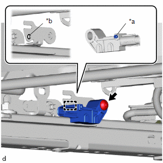
(a) Insert the pin into the installation hole and temporarily install the seat position airbag sensor to the seat rail bracket with the bolt as shown in the illustration. |
|
|
(b) Using a T30 "TORX" socket wrench and a 1.3 mm (0.0512 in.) feeler gauge, install the seat position airbag sensor with the "TORX" bolt. Torque: 8.0 N·m {82 kgf·cm, 71 in·lbf} NOTICE:
|
|
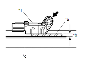
(c) Make sure that the clearance between the seat position airbag sensor and seat track bracket is 1.3 mm (0.0512 in.).
(d) Check that there is no looseness in the installed parts of the seat position airbag sensor.
2. INSTALL SEAT SLIDE POSITION SENSOR PROTECTOR
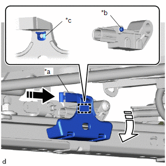
(a) Insert the seat slide position sensor protector to the seat rail bracket and engage the pin to the installation part of the seat slide position sensor protector.
|
*a |
Seat Rail Bracket |
|
*b |
Pin |
|
*c |
Installation Part |
.png) |
Install in this Direction (1) |
.png) |
Install in this Direction (2) |
|
(b) Connect the connector and engage the clamp. |
|
.png)
3. INSTALL FRONT SEAT ASSEMBLY
Click here .gif)
 Removal
REMOVAL
CAUTION / NOTICE / HINT
The necessary procedures (adjustment, calibration, initialization, or registration)
that must be performed after parts are removed, installed, or replaced during th ...

Other materials:
Toyota CH-R Owners Manual > Do-it-yourself maintenance: Positioning a floor jack
When using a floor jack, follow the instructions in the manual provided
with the jack and perform the operation safely.
When raising your vehicle with a floor jack, position the jack correctly.
Improper placement may damage your vehicle or cause injury.
Front
Rear
...
Toyota CH-R Owners Manual > BSM (Blind Spot Monitor): Summary of the Blind Spot Monitor
The Blind Spot Monitor is a system that has 2 functions;
The BSM (Blind Spot Monitor) function
Assists the driver in making the decision when changing lanes
The RCTA (Rear Cross Traffic Alert) function
Assists the driver when backing up
These functions use same sensors.
Outside ...
Toyota C-HR (AX20) 2023-2026 Owner's Manual
Toyota CH-R Owners Manual
- For safety and security
- Instrument cluster
- Operation of each component
- Driving
- Interior features
- Maintenance and care
- When trouble arises
- Vehicle specifications
- For owners
Toyota CH-R Service Manual
- Introduction
- Maintenance
- Audio / Video
- Cellular Communication
- Navigation / Multi Info Display
- Park Assist / Monitoring
- Brake (front)
- Brake (rear)
- Brake Control / Dynamic Control Systems
- Brake System (other)
- Parking Brake
- Axle And Differential
- Drive Shaft / Propeller Shaft
- K114 Cvt
- 3zr-fae Battery / Charging
- Networking
- Power Distribution
- Power Assist Systems
- Steering Column
- Steering Gear / Linkage
- Alignment / Handling Diagnosis
- Front Suspension
- Rear Suspension
- Tire / Wheel
- Tire Pressure Monitoring
- Door / Hatch
- Exterior Panels / Trim
- Horn
- Lighting (ext)
- Mirror (ext)
- Window / Glass
- Wiper / Washer
- Door Lock
- Heating / Air Conditioning
- Interior Panels / Trim
- Lighting (int)
- Meter / Gauge / Display
- Mirror (int)
- Power Outlets (int)
- Pre-collision
- Seat
- Seat Belt
- Supplemental Restraint Systems
- Theft Deterrent / Keyless Entry

0.0118