Toyota CH-R Service Manual: Radio Receiver(for Radio Receiver Type)
Components
COMPONENTS
ILLUSTRATION
|
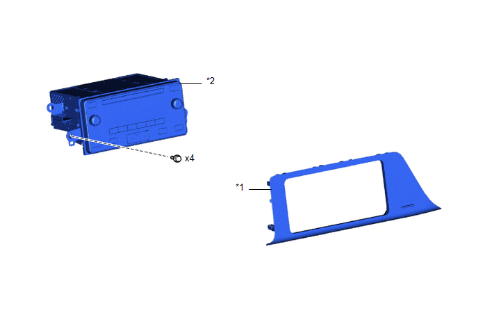
*1 |
INSTRUMENT CLUSTER FINISH CENTER PANEL SUB-ASSEMBLY |
*2 |
RADIO RECEIVER ASSEMBLY WITH BRACKET |
ILLUSTRATION
|
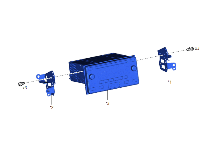
*1 |
NO. 1 RADIO BRACKET |
*2 |
NO. 2 RADIO BRACKET |
|
*3 |
RADIO RECEIVER ASSEMBLY |
- |
- |
Removal
REMOVAL
PROCEDURE
1. REMOVE INSTRUMENT CLUSTER FINISH CENTER PANEL SUB-ASSEMBLY
Click here
.gif)
2. REMOVE RADIO RECEIVER ASSEMBLY WITH BRACKET
|
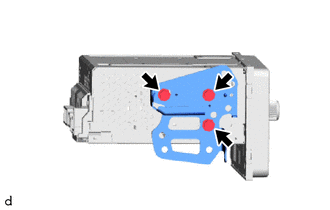
(a) Remove the 4 screws. |
|
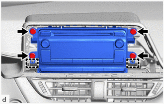
(b) Pull the radio receiver assembly with bracket toward the rear of the vehicle to disengage the guides.
(c) Disconnect each connector and remove the radio receiver assembly with bracket.
3. REMOVE NO. 1 RADIO BRACKET
|
(a) Remove the 3 screws and No. 1 radio bracket from the radio receiver assembly. |
|
4. REMOVE NO. 2 RADIO BRACKET
|
(a) Remove the 3 screws and No. 2 radio bracket from the radio receiver assembly. |
|
Installation
INSTALLATION
PROCEDURE
1. INSTALL NO. 2 RADIO BRACKET
(a) Install the No. 2 radio bracket with the 3 screws to the radio receiver assembly.
2. INSTALL NO. 1 RADIO BRACKET
(a) Install the No. 1 radio bracket with the 3 screws to the radio receiver assembly.
3. INSTALL RADIO RECEIVER ASSEMBLY WITH BRACKET
(a) Connect each connector.
|
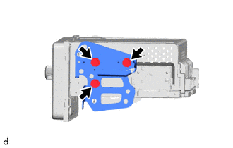
(b) Engage the guides to temporarily install the radio receiver assembly with bracket. |
|
.png)
(c) Install the radio receiver assembly with bracket with the 4 screws.
4. INSTALL INSTRUMENT CLUSTER FINISH CENTER PANEL SUB-ASSEMBLY
Click here
.gif)
 Removal
REMOVAL
CAUTION / NOTICE / HINT
The necessary procedures (adjustment, calibration, initialization, or registration)
that must be performed after parts are removed and installed, or replaced the du ...
 Radio Receiver(for Radio And Display Type)
Components
COMPONENTS
ILLUSTRATION
*1
INSTRUMENT CLUSTER FINISH LOWER CENTER PANEL SUB-ASSEMBLY
*2
INSTRUMENT CLUSTER FINISH PANEL GARNISH ASSEMBLY
...
Other materials:
Toyota CH-R Service Manual > Door Control Switch: Removal
REMOVAL
PROCEDURE
1. REMOVE MULTIPLEX NETWORK MASTER SWITCH ASSEMBLY WITH FRONT ARMREST BASE UPPER
PANEL (for Driver Side)
Click here
2. REMOVE POWER WINDOW REGULATOR SWITCH ASSEMBLY WITH FRONT ARMREST BASE UPPER
PANEL (for Front Passenger Side)
Click here
3. REMOVE MULTIPLEX NETWO ...
Toyota CH-R Owners Manual > Engine compartment: Battery
Check the battery as follows.
■ Battery exterior Make sure that the battery terminals are
not corroded and that there are no loose connections, cracks, or loose clamps.
Terminals
Hold-down clamp
■ Checking battery fluid If there are lines on the side of the
battery: Check that ...
Toyota C-HR (AX20) 2023-2025 Owner's Manual
Toyota CH-R Owners Manual
- For safety and security
- Instrument cluster
- Operation of each component
- Driving
- Interior features
- Maintenance and care
- When trouble arises
- Vehicle specifications
- For owners
Toyota CH-R Service Manual
- Introduction
- Maintenance
- Audio / Video
- Cellular Communication
- Navigation / Multi Info Display
- Park Assist / Monitoring
- Brake (front)
- Brake (rear)
- Brake Control / Dynamic Control Systems
- Brake System (other)
- Parking Brake
- Axle And Differential
- Drive Shaft / Propeller Shaft
- K114 Cvt
- 3zr-fae Battery / Charging
- Networking
- Power Distribution
- Power Assist Systems
- Steering Column
- Steering Gear / Linkage
- Alignment / Handling Diagnosis
- Front Suspension
- Rear Suspension
- Tire / Wheel
- Tire Pressure Monitoring
- Door / Hatch
- Exterior Panels / Trim
- Horn
- Lighting (ext)
- Mirror (ext)
- Window / Glass
- Wiper / Washer
- Door Lock
- Heating / Air Conditioning
- Interior Panels / Trim
- Lighting (int)
- Meter / Gauge / Display
- Mirror (int)
- Power Outlets (int)
- Pre-collision
- Seat
- Seat Belt
- Supplemental Restraint Systems
- Theft Deterrent / Keyless Entry

0.0125