Toyota CH-R Service Manual: Removal
REMOVAL
PROCEDURE
1. REMOVE MULTIPLEX NETWORK MASTER SWITCH ASSEMBLY WITH FRONT ARMREST BASE UPPER PANEL (for Driver Side)
Click here
.gif)
2. REMOVE POWER WINDOW REGULATOR SWITCH ASSEMBLY WITH FRONT ARMREST BASE UPPER PANEL (for Front Passenger Side)
Click here
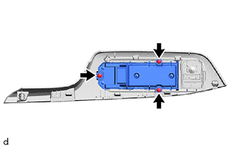
3. REMOVE MULTIPLEX NETWORK MASTER SWITCH ASSEMBLY (for Driver Side)
|
(a) Remove the 3 screws and multiplex network master switch assembly. |
|
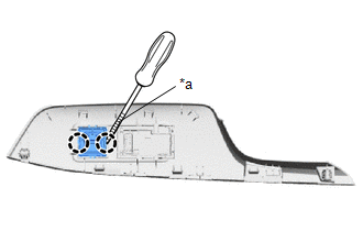
4. REMOVE DOOR CONTROL SWITCH ASSEMBLY (for Front Passenger Side)
|
(a) Using a screwdriver with its tip wrapped in protective tape, disengage the claws to remove the door control switch assembly. |
|
 Inspection
INSPECTION
PROCEDURE
1. INSPECT MULTIPLEX NETWORK MASTER SWITCH ASSEMBLY
(a) Check that the LED illuminates.
(1) Apply battery voltage to the multiplex network master switch assembly
...
 Installation
INSTALLATION
PROCEDURE
1. INSTALL MULTIPLEX NETWORK MASTER SWITCH ASSEMBLY (for Driver Side)
(a) Install the multiplex network master switch assembly with the 3 screws.
2. INSTALL DOOR CONTROL SWI ...
Other materials:
Toyota CH-R Service Manual > Navigation System: Does not Play even after Bluetooth Audio Mode is Selected
CAUTION / NOTICE / HINT
NOTICE:
Depending on the parts that are replaced during vehicle inspection or
maintenance, performing initialization, registration or calibration may
be needed. Refer to Precaution for Navigation System.
Click here
When replacing the radio ...
Toyota CH-R Service Manual > Air Conditioning Amplifier: Components
COMPONENTS
ILLUSTRATION
*A
for DENSO Made
*B
for VALEO Made
*1
AIR CONDITIONING AMPLIFIER ASSEMBLY
*2
COWL SIDE TRIM BOARD LH
*3
FRONT DOOR SCUFF PLATE LH
*4
...
Toyota C-HR (AX20) 2023-2026 Owner's Manual
Toyota CH-R Owners Manual
- For safety and security
- Instrument cluster
- Operation of each component
- Driving
- Interior features
- Maintenance and care
- When trouble arises
- Vehicle specifications
- For owners
Toyota CH-R Service Manual
- Introduction
- Maintenance
- Audio / Video
- Cellular Communication
- Navigation / Multi Info Display
- Park Assist / Monitoring
- Brake (front)
- Brake (rear)
- Brake Control / Dynamic Control Systems
- Brake System (other)
- Parking Brake
- Axle And Differential
- Drive Shaft / Propeller Shaft
- K114 Cvt
- 3zr-fae Battery / Charging
- Networking
- Power Distribution
- Power Assist Systems
- Steering Column
- Steering Gear / Linkage
- Alignment / Handling Diagnosis
- Front Suspension
- Rear Suspension
- Tire / Wheel
- Tire Pressure Monitoring
- Door / Hatch
- Exterior Panels / Trim
- Horn
- Lighting (ext)
- Mirror (ext)
- Window / Glass
- Wiper / Washer
- Door Lock
- Heating / Air Conditioning
- Interior Panels / Trim
- Lighting (int)
- Meter / Gauge / Display
- Mirror (int)
- Power Outlets (int)
- Pre-collision
- Seat
- Seat Belt
- Supplemental Restraint Systems
- Theft Deterrent / Keyless Entry

0.0139