Toyota CH-R Service Manual: Engine Hood Courtesy Switch
Components
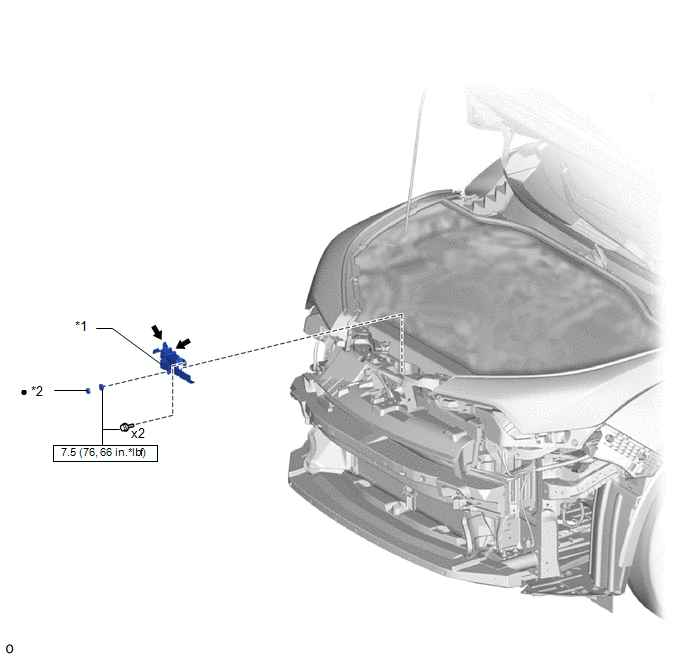
COMPONENTS
ILLUSTRATION
|
*1 |
ENGINE HOOD COURTESY SWITCH (HOOD LOCK ASSEMBLY) |
*2 |
HOOD LOCK NUT CAP |
.png) |
N*m (kgf*cm, ft.*lbf): Specified torque |
● |
Non-reusable part |
.png) |
MP grease |
- |
- |
Removal
REMOVAL
PROCEDURE
1. REMOVE FRONT BUMPER ASSEMBLY
Click here .gif)
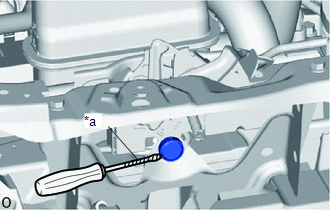
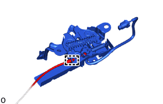
2. REMOVE HOOD LOCK NUT CAP
|
(a) Using a screwdriver with its tip wrapped in protective tape, remove the hood lock nut cap. |
|
3. REMOVE ENGINE HOOD COURTESY SWITCH (HOOD LOCK ASSEMBLY)
|
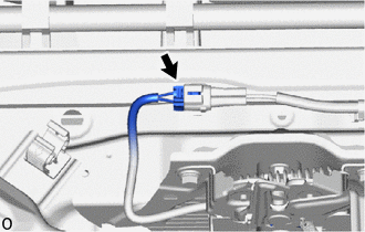
(a) Disconnect the connector. |
|
|
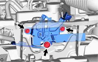
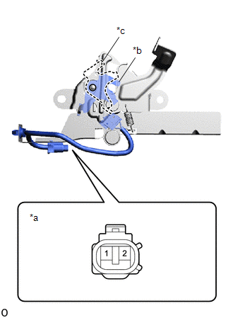
(b) Remove the 2 bolts and hood lock bolt to separate the engine hood courtesy switch (hood lock assembly). |
|
|
(c) Disengage the guide. |
|
(d) Disconnect the hood lock control cable assembly to remove the hood courtesy switch (hood lock assembly).
Inspection
INSPECTION
PROCEDURE
1. INSPECT ENGINE HOOD COURTESY SWITCH (HOOD LOCK ASSEMBLY)
|
(a) Check the resistance. (1) Measure the resistance according to the value(s) in the table below. Standard Resistance:
If the resistance is not as specified, replace the engine hood courtesy switch (hood lock assembly). |
|
Installation
INSTALLATION
PROCEDURE
1. INSTALL ENGINE HOOD COURTESY SWITCH (HOOD LOCK ASSEMBLY)
|
(a) Engage the guide to connect the hood lock control cable assembly. |
|
.png)
(b) Install the hood courtesy switch (hood lock assembly) with the 2 bolts and hood lock bolt.
Torque:
7.5 N·m {76 kgf·cm, 66 in·lbf}
(c) Connect the connector.
2. INSTALL HOOD LOCK NUT CAP
(a) Install a new hood lock nut cap.
3. INSTALL FRONT BUMPER ASSEMBLY
Click here .gif)
 Electrical Key Oscillator(for Rear Floor)
Components
COMPONENTS
ILLUSTRATION
*1
BENCH TYPE REAR SEAT CUSHION ASSEMBLY
*2
NO. 2 INDOOR ELECTRICAL KEY ANTENNA ASSEMBLY
*3
...
 Id Code Box
...
Other materials:
Toyota CH-R Service Manual > Window Defogger System: Parts Location
PARTS LOCATION
ILLUSTRATION
*1
DEF RELAY
*2
BACK DOOR GLASS (REAR WINDOW DEFOGGER WIRE)
*3
NO. 1 ENGINE ROOM RELAY BLOCK
*4
DEF FUSE
ILLUSTRATION
*A
for TMMT Made
...
Toyota CH-R Service Manual > Vehicle Stability Control System: ABS does not Operate
DESCRIPTION
When the vehicle stability control system is operating, as the input piston and
output piston are not directly connected, the kickback of the brake pedal is minimal
during ABS operation and the driver may not notice that ABS operated.
CAUTION / NOTICE / HINT
NOTICE:
When replacin ...
Toyota C-HR (AX20) 2023-2026 Owner's Manual
Toyota CH-R Owners Manual
- For safety and security
- Instrument cluster
- Operation of each component
- Driving
- Interior features
- Maintenance and care
- When trouble arises
- Vehicle specifications
- For owners
Toyota CH-R Service Manual
- Introduction
- Maintenance
- Audio / Video
- Cellular Communication
- Navigation / Multi Info Display
- Park Assist / Monitoring
- Brake (front)
- Brake (rear)
- Brake Control / Dynamic Control Systems
- Brake System (other)
- Parking Brake
- Axle And Differential
- Drive Shaft / Propeller Shaft
- K114 Cvt
- 3zr-fae Battery / Charging
- Networking
- Power Distribution
- Power Assist Systems
- Steering Column
- Steering Gear / Linkage
- Alignment / Handling Diagnosis
- Front Suspension
- Rear Suspension
- Tire / Wheel
- Tire Pressure Monitoring
- Door / Hatch
- Exterior Panels / Trim
- Horn
- Lighting (ext)
- Mirror (ext)
- Window / Glass
- Wiper / Washer
- Door Lock
- Heating / Air Conditioning
- Interior Panels / Trim
- Lighting (int)
- Meter / Gauge / Display
- Mirror (int)
- Power Outlets (int)
- Pre-collision
- Seat
- Seat Belt
- Supplemental Restraint Systems
- Theft Deterrent / Keyless Entry

0.0077