Toyota CH-R Service Manual: Electrical Key Oscillator(for Rear Floor)
Components
COMPONENTS
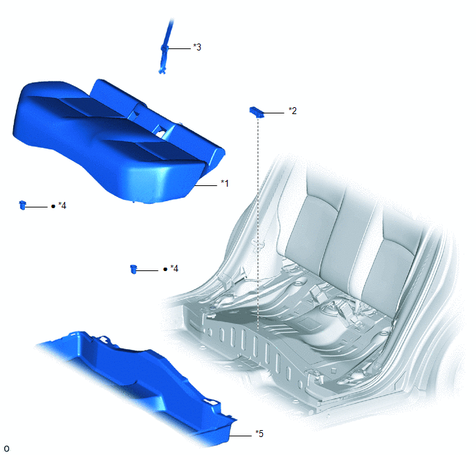
ILLUSTRATION
|
*1 |
BENCH TYPE REAR SEAT CUSHION ASSEMBLY |
*2 |
NO. 2 INDOOR ELECTRICAL KEY ANTENNA ASSEMBLY |
|
*3 |
REAR CENTER SEAT OUTER BELT ASSEMBLY |
*4 |
REAR SEAT CUSHION LOCK HOOK |
|
*5 |
FRONT FLOOR CARPET ASSEMBLY |
- |
- |
|
● |
Non-reusable part |
- |
- |
Removal
REMOVAL
PROCEDURE
1. DISCONNECT REAR CENTER SEAT OUTER BELT ASSEMBLY
Click here .gif)
2. REMOVE BENCH TYPE REAR SEAT CUSHION ASSEMBLY
Click here
3. REMOVE REAR SEAT CUSHION LOCK HOOK
Click here
4. REMOVE NO. 2 INDOOR ELECTRICAL KEY ANTENNA ASSEMBLY
(a) Peel back the front floor carpet assembly to the extent that the No. 2 indoor electrical key antenna assembly can be removed.
(b) Disconnect the connector.
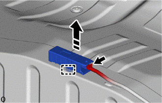
.png) |
Remove in this Direction |
(c) Using a clip remover, disengage the clamp to remove the No. 2 indoor electrical key antenna assembly as shown in the illustration.
NOTICE:
Be careful when removing the No. 2 indoor electrical key antenna assembly. If the No. 2 indoor electrical key antenna assembly is dropped, replace it with a new one.
Installation
INSTALLATION
PROCEDURE
1. INSTALL NO. 2 INDOOR ELECTRICAL KEY ANTENNA ASSEMBLY
(a) Engage the clamp to install the No. 2 indoor electrical key antenna assembly as shown in the illustration.
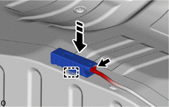
.png) |
Install in this Direction |
NOTICE:
Be careful when installing the No. 2 indoor electrical key antenna assembly. If the No. 2 indoor electrical key antenna assembly is dropped, replace it with a new one.
(b) Connect the connector.
(c) Return the front floor carpet assembly.
2. INSTALL REAR SEAT CUSHION LOCK HOOK
Click here .gif)
3. INSTALL BENCH TYPE REAR SEAT CUSHION ASSEMBLY
Click here
4. CONNECT REAR CENTER SEAT OUTER BELT ASSEMBLY
Click here
 Electrical Key Oscillator(for Outside Luggage Compartment)
Components
COMPONENTS
ILLUSTRATION
*1
ELECTRICAL KEY ANTENNA
-
-
N*m (kgf*cm, ft.*lbf): Specified torque
-
...
 Engine Hood Courtesy Switch
Components
COMPONENTS
ILLUSTRATION
*1
ENGINE HOOD COURTESY SWITCH (HOOD LOCK ASSEMBLY)
*2
HOOD LOCK NUT CAP
N*m (kgf*cm, ft ...
Other materials:
Toyota CH-R Service Manual > Rear Shock Absorber: Installation
INSTALLATION
CAUTION / NOTICE / HINT
HINT:
Use the same procedure for the RH side and LH side.
The following procedure is for the LH side.
PROCEDURE
1. INSTALL REAR SUSPENSION SUPPORT ASSEMBLY
(a) Secure the rear suspension support assembly in a vise using aluminum plates.
N ...
Toyota CH-R Service Manual > Immobiliser System(w/ Smart Key System): ID BOX EEPROM Malfunction (B2790)
DESCRIPTION
When an internal malfunction occurs in the ID code box (immobiliser code ECU),
the certification ECU (smart key ECU assembly) stores this DTC.
DTC No.
Detection Item
DTC Detection Condition
Trouble Area
Note
B279 ...
Toyota C-HR (AX20) 2023-2026 Owner's Manual
Toyota CH-R Owners Manual
- For safety and security
- Instrument cluster
- Operation of each component
- Driving
- Interior features
- Maintenance and care
- When trouble arises
- Vehicle specifications
- For owners
Toyota CH-R Service Manual
- Introduction
- Maintenance
- Audio / Video
- Cellular Communication
- Navigation / Multi Info Display
- Park Assist / Monitoring
- Brake (front)
- Brake (rear)
- Brake Control / Dynamic Control Systems
- Brake System (other)
- Parking Brake
- Axle And Differential
- Drive Shaft / Propeller Shaft
- K114 Cvt
- 3zr-fae Battery / Charging
- Networking
- Power Distribution
- Power Assist Systems
- Steering Column
- Steering Gear / Linkage
- Alignment / Handling Diagnosis
- Front Suspension
- Rear Suspension
- Tire / Wheel
- Tire Pressure Monitoring
- Door / Hatch
- Exterior Panels / Trim
- Horn
- Lighting (ext)
- Mirror (ext)
- Window / Glass
- Wiper / Washer
- Door Lock
- Heating / Air Conditioning
- Interior Panels / Trim
- Lighting (int)
- Meter / Gauge / Display
- Mirror (int)
- Power Outlets (int)
- Pre-collision
- Seat
- Seat Belt
- Supplemental Restraint Systems
- Theft Deterrent / Keyless Entry

0.0082