Toyota CH-R Service Manual: Parts Location
PARTS LOCATION
ILLUSTRATION
|
*A |
w/ Navigation System |
- |
- |
|
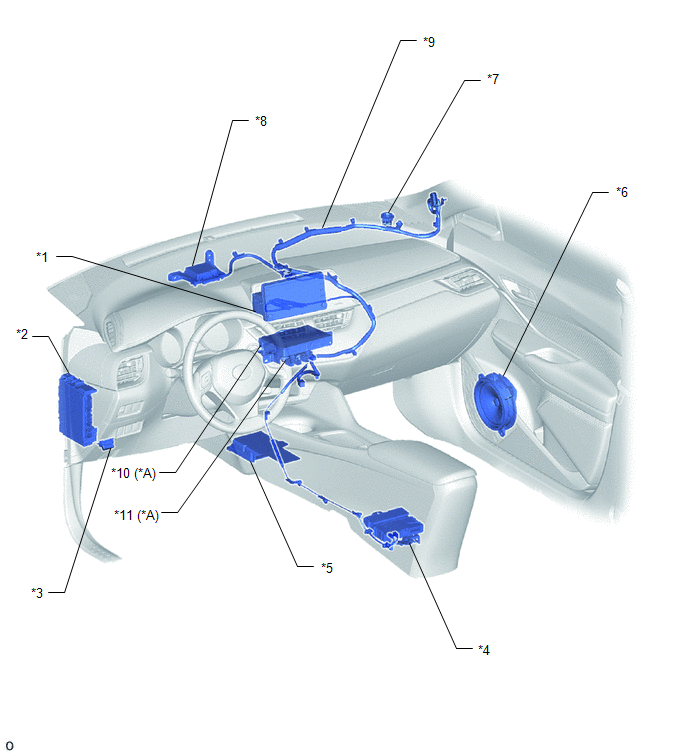
*1 |
RADIO AND DISPLAY RECEIVER ASSEMBLY |
*2 |
INSTRUMENT PANEL JUNCTION BLOCK ASSEMBLY - ECU-ACC FUSE - ECU-IG2 NO. 3 FUSE |
|
*3 |
DLC3 |
*4 |
DCM (TELEMATICS TRANSCEIVER) |
|
*5 |
AIRBAG SENSOR ASSEMBLY |
*6 |
FRONT NO. 1 SPEAKER ASSEMBLY RH |
|
*7 |
FRONT NO. 2 SPEAKER ASSEMBLY RH |
*8 |
TELEPHONE AND GPS ANTENNA ASSEMBLY (for Front Side) - Telephone Sub |
|
*9 |
TELEPHONE AND GPS ANTENNA CORD (ANTENNA CORD SUB-ASSEMBLY) |
*10 |
NAVIGATION ECU |
|
*11 |
NO. 1 NAVIGATION WIRE |
- |
- |
ILLUSTRATION
|
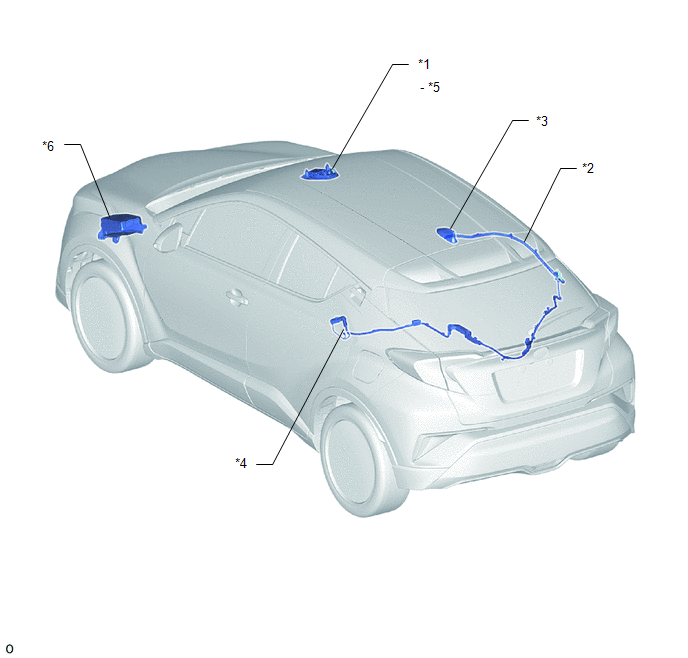
*1 |
MAP LIGHT ASSEMBLY - TELEPHONE MICROPHONE ASSEMBLY |
*2 |
TELEPHONE AND GPS ANTENNA CORD (NO. 3 ANTENNA CORD SUB-ASSEMBLY) |
|
*3 |
TELEPHONE AND GPS ANTENNA ASSEMBLY (for Roof Side) |
*4 |
TELEPHONE AND GPS ANTENNA CORD (NO. 6 ANTENNA CORD SUB-ASSEMBLY) - GPS - Telephone Main |
|
*5 |
MAYDAY SWITCH ASSEMBLY (MANUAL (SOS) SWITCH) |
*6 |
NO. 1 ENGINE ROOM RELAY BLOCK - DCM/MAYDAY FUSE |
 Precaution
PRECAUTION
IGNITION SWITCH EXPRESSIONS
(a) The type of ignition switch used on this model differs according to the specifications
of the vehicle. The expressions listed in the table below are used ...
 System Diagram
SYSTEM DIAGRAM
...
Other materials:
Toyota CH-R Service Manual > Brake Control / Dynamic Control Systems: Brake Hold Switch
Components
COMPONENTS
ILLUSTRATION
*1
BRAKE HOLD SWITCH (ELECTRIC PARKING BRAKE SWITCH ASSEMBLY)
-
-
Inspection
INSPECTION
PROCEDURE
1. INSPECT BRAKE HOLD SWITCH (ELECTRIC PARKING BRAKE SWITCH ASSEMBLY)
(a) Check the resistance.
...
Toyota CH-R Service Manual > Headlight Dimmer Switch: Components
COMPONENTS
ILLUSTRATION
*1
HEADLIGHT DIMMER SWITCH ASSEMBLY
*2
WINDSHIELD WIPER SWITCH ASSEMBLY
...
Toyota C-HR (AX20) 2023-2026 Owner's Manual
Toyota CH-R Owners Manual
- For safety and security
- Instrument cluster
- Operation of each component
- Driving
- Interior features
- Maintenance and care
- When trouble arises
- Vehicle specifications
- For owners
Toyota CH-R Service Manual
- Introduction
- Maintenance
- Audio / Video
- Cellular Communication
- Navigation / Multi Info Display
- Park Assist / Monitoring
- Brake (front)
- Brake (rear)
- Brake Control / Dynamic Control Systems
- Brake System (other)
- Parking Brake
- Axle And Differential
- Drive Shaft / Propeller Shaft
- K114 Cvt
- 3zr-fae Battery / Charging
- Networking
- Power Distribution
- Power Assist Systems
- Steering Column
- Steering Gear / Linkage
- Alignment / Handling Diagnosis
- Front Suspension
- Rear Suspension
- Tire / Wheel
- Tire Pressure Monitoring
- Door / Hatch
- Exterior Panels / Trim
- Horn
- Lighting (ext)
- Mirror (ext)
- Window / Glass
- Wiper / Washer
- Door Lock
- Heating / Air Conditioning
- Interior Panels / Trim
- Lighting (int)
- Meter / Gauge / Display
- Mirror (int)
- Power Outlets (int)
- Pre-collision
- Seat
- Seat Belt
- Supplemental Restraint Systems
- Theft Deterrent / Keyless Entry

0.0078