Toyota CH-R Service Manual: System Diagram
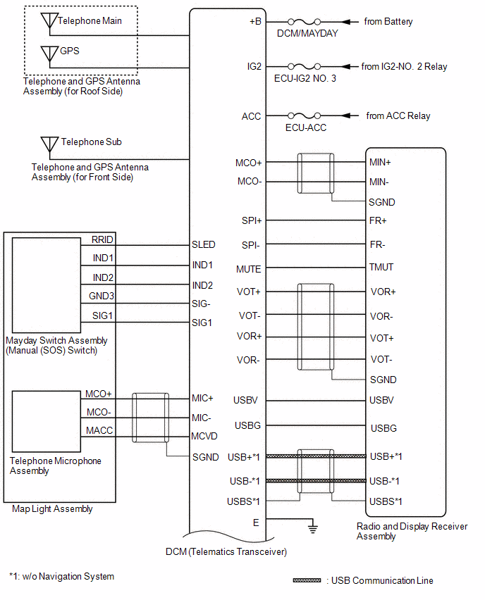
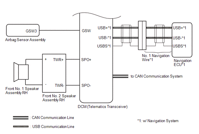
SYSTEM DIAGRAM
 Parts Location
PARTS LOCATION
ILLUSTRATION
*A
w/ Navigation System
-
-
*1
RADIO AND DISPLAY RECEIVER ASSEMBLY
*2
INST ...
 System Description
SYSTEM DESCRIPTION
DESCRIPTION
(a) Safety Connect performs ACN (Automatic Collision Notification), manual emergency
calling, stolen vehicle tracking and roadside assistance service by, audio and d ...
Other materials:
Toyota CH-R Service Manual > 3zr-fae Battery / Charging: Battery
Components
COMPONENTS
ILLUSTRATION
*1
BATTERY
*2
NO. 2 BATTERY CLAMP
*3
POSITIVE BATTERY TERMINAL
*4
NEGATIVE BATTERY TERMINAL
*5
FUSIBLE LINK COVER
*6
...
Toyota CH-R Service Manual > Steering Lock System: Power Source Control ECU Malfunction (B2782)
DESCRIPTION
The certification ECU (smart key ECU assembly) has a power source mode switching
function.
This DTC is stored when the IGEI input (the steering lock motor activation permission
signal) sent directly from the certification ECU (smart key ECU assembly) to the
steering lock ECU (ste ...
Toyota C-HR (AX20) 2023-2026 Owner's Manual
Toyota CH-R Owners Manual
- For safety and security
- Instrument cluster
- Operation of each component
- Driving
- Interior features
- Maintenance and care
- When trouble arises
- Vehicle specifications
- For owners
Toyota CH-R Service Manual
- Introduction
- Maintenance
- Audio / Video
- Cellular Communication
- Navigation / Multi Info Display
- Park Assist / Monitoring
- Brake (front)
- Brake (rear)
- Brake Control / Dynamic Control Systems
- Brake System (other)
- Parking Brake
- Axle And Differential
- Drive Shaft / Propeller Shaft
- K114 Cvt
- 3zr-fae Battery / Charging
- Networking
- Power Distribution
- Power Assist Systems
- Steering Column
- Steering Gear / Linkage
- Alignment / Handling Diagnosis
- Front Suspension
- Rear Suspension
- Tire / Wheel
- Tire Pressure Monitoring
- Door / Hatch
- Exterior Panels / Trim
- Horn
- Lighting (ext)
- Mirror (ext)
- Window / Glass
- Wiper / Washer
- Door Lock
- Heating / Air Conditioning
- Interior Panels / Trim
- Lighting (int)
- Meter / Gauge / Display
- Mirror (int)
- Power Outlets (int)
- Pre-collision
- Seat
- Seat Belt
- Supplemental Restraint Systems
- Theft Deterrent / Keyless Entry

0.0151