Toyota CH-R Service Manual: On-vehicle Inspection
ON-VEHICLE INSPECTION
CAUTION / NOTICE / HINT
HINT:
- Use the same procedure for the RH side and LH side.
- The following procedure is for the LH side.
PROCEDURE
1. REMOVE FRONT WHEEL
Click here
.gif)
2. SEPARATE FRONT DISC BRAKE CALIPER ASSEMBLY
Click here
3. REMOVE FRONT DISC
Click here
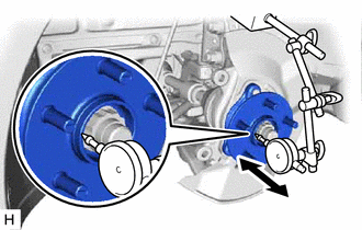
4. INSPECT FRONT AXLE HUB BEARING LOOSENESS
|
(a) Using a dial indicator, check for looseness near the center of the front axle hub sub-assembly. Maximum Looseness: 0.05 mm (0.00196 in.) NOTICE:
|
|
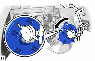
5. INSPECT FRONT AXLE HUB RUNOUT
|
(a) Using a dial indicator, check for runout on the surface of the front axle hub sub-assembly outside the front axle hub bolts. Maximum Runout: 0.05 mm (0.00196 in.) NOTICE:
|
|
6. INSTALL FRONT DISC
Click here
7. INSTALL FRONT DISC BRAKE CALIPER ASSEMBLY
Click here
8. INSTALL FRONT WHEEL
Click here
 Components
COMPONENTS
ILLUSTRATION
*1
FRONT AXLE ASSEMBLY
*2
FRONT AXLE SHAFT NUT
*3
FRONT DISC
*4
FRONT DISC BRA ...
 Installation
INSTALLATION
CAUTION / NOTICE / HINT
HINT:
Use the same procedure for the RH side and LH side.
The following procedure is for the LH side.
PROCEDURE
1. INSTALL FRONT AXLE HUB SU ...
Other materials:
Toyota CH-R Service Manual > Vehicle Stability Control System: TC and CG Terminal Circuit
DESCRIPTION
Connecting terminals TC and CG of the DLC3 causes the ECU to display DTCs by
blinking the ABS warning and slip indicator lights.
WIRING DIAGRAM
CAUTION / NOTICE / HINT
NOTICE:
When replacing the skid control ECU (brake actuator assembly), perform system
variant learning.
Clic ...
Toyota CH-R Service Manual > Navigation System: Vehicle Speed Signal Circuit between Navigation ECU and Combination Meter
DESCRIPTION
The navigation ECU receives a vehicle speed signal from the combination meter
assembly.
HINT:
A voltage of 12 V or 5 V is output from each ECU and then input to the
combination meter assembly. The signal is changed to a pulse signal at the
transistor in the combinati ...
Toyota C-HR (AX20) 2023-2026 Owner's Manual
Toyota CH-R Owners Manual
- For safety and security
- Instrument cluster
- Operation of each component
- Driving
- Interior features
- Maintenance and care
- When trouble arises
- Vehicle specifications
- For owners
Toyota CH-R Service Manual
- Introduction
- Maintenance
- Audio / Video
- Cellular Communication
- Navigation / Multi Info Display
- Park Assist / Monitoring
- Brake (front)
- Brake (rear)
- Brake Control / Dynamic Control Systems
- Brake System (other)
- Parking Brake
- Axle And Differential
- Drive Shaft / Propeller Shaft
- K114 Cvt
- 3zr-fae Battery / Charging
- Networking
- Power Distribution
- Power Assist Systems
- Steering Column
- Steering Gear / Linkage
- Alignment / Handling Diagnosis
- Front Suspension
- Rear Suspension
- Tire / Wheel
- Tire Pressure Monitoring
- Door / Hatch
- Exterior Panels / Trim
- Horn
- Lighting (ext)
- Mirror (ext)
- Window / Glass
- Wiper / Washer
- Door Lock
- Heating / Air Conditioning
- Interior Panels / Trim
- Lighting (int)
- Meter / Gauge / Display
- Mirror (int)
- Power Outlets (int)
- Pre-collision
- Seat
- Seat Belt
- Supplemental Restraint Systems
- Theft Deterrent / Keyless Entry

0.0122