Toyota CH-R Service Manual: Components
COMPONENTS
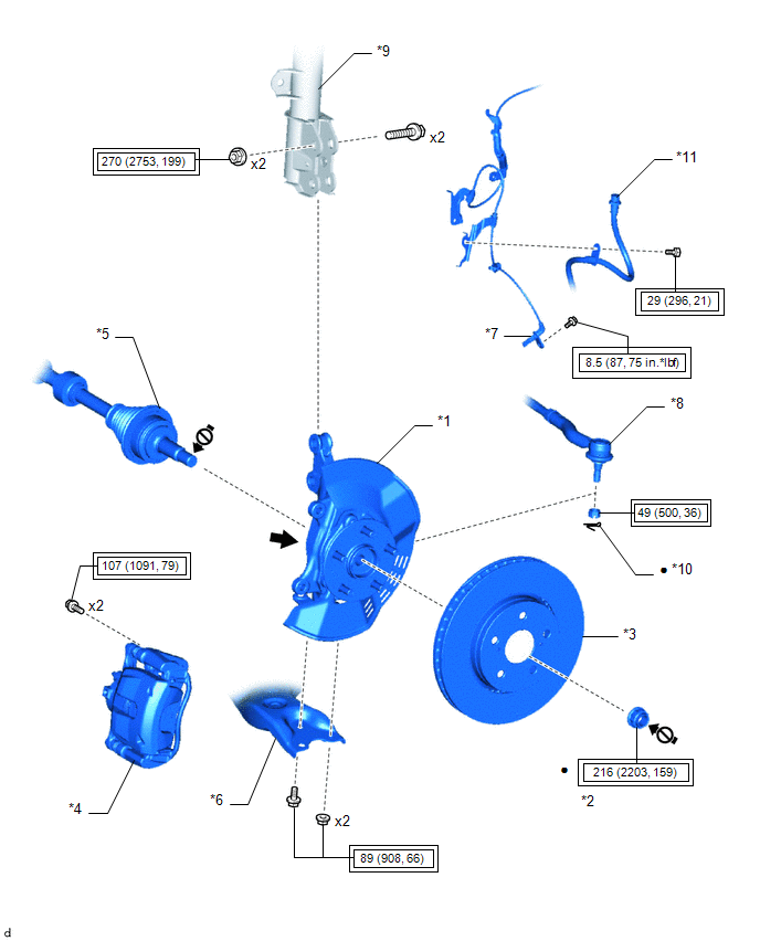
ILLUSTRATION
|
*1 |
FRONT AXLE ASSEMBLY |
*2 |
FRONT AXLE SHAFT NUT |
|
*3 |
FRONT DISC |
*4 |
FRONT DISC BRAKE CALIPER ASSEMBLY |
|
*5 |
FRONT DRIVE SHAFT ASSEMBLY |
*6 |
FRONT LOWER NO. 1 SUSPENSION ARM SUB-ASSEMBLY |
|
*7 |
FRONT SPEED SENSOR |
*8 |
TIE ROD END SUB-ASSEMBLY |
|
*9 |
FRONT SHOCK ABSORBER ASSEMBLY |
*10 |
COTTER PIN |
|
*11 |
FRONT FLEXIBLE HOSE |
- |
- |
.png) |
Tightening torque for "Major areas involving basic vehicle performance such as moving/turning/stopping" : N*m (kgf*cm, ft.*lbf) |
● |
Non-reusable part |
.png) |
Toyota Body Grease W |
.png) |
Do not apply lubricants to the threaded parts |
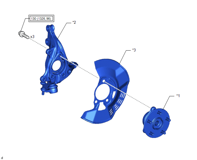
ILLUSTRATION
|
*1 |
FRONT AXLE HUB SUB-ASSEMBLY |
*2 |
STEERING KNUCKLE |
|
*3 |
FRONT DISC BRAKE DUST COVER |
- |
- |
|
|
Tightening torque for "Major areas involving basic vehicle performance such as moving/turning/stopping" : N*m (kgf*cm, ft.*lbf) |
- |
- |
 Front Axle Hub
...
 On-vehicle Inspection
ON-VEHICLE INSPECTION
CAUTION / NOTICE / HINT
HINT:
Use the same procedure for the RH side and LH side.
The following procedure is for the LH side.
PROCEDURE
1. REMOVE FRONT WHE ...
Other materials:
Toyota CH-R Service Manual > Theft Deterrent / Keyless Entry: Electrical Key Oscillator(for Front Floor)
Components
COMPONENTS
ILLUSTRATION
*1
NO. 1 INDOOR ELECTRICAL KEY ANTENNA ASSEMBLY
-
-
Installation
INSTALLATION
PROCEDURE
1. INSTALL NO. 1 INDOOR ELECTRICAL KEY ANTENNA ASSEMBLY
(a) Engage the clamp to install the No. 1 indoor elect ...
Toyota CH-R Service Manual > Inner Rear View Mirror: Installation
INSTALLATION
PROCEDURE
1. INSTALL INNER REAR VIEW MIRROR ASSEMBLY (w/o Pre-collision System)
(a) Install the inner rear view mirror assembly as shown in the illustration.
Install in this Direction
(b) Using a T20 "TORX" socket wrench, install the screw.
...
Toyota C-HR (AX20) 2023-2026 Owner's Manual
Toyota CH-R Owners Manual
- For safety and security
- Instrument cluster
- Operation of each component
- Driving
- Interior features
- Maintenance and care
- When trouble arises
- Vehicle specifications
- For owners
Toyota CH-R Service Manual
- Introduction
- Maintenance
- Audio / Video
- Cellular Communication
- Navigation / Multi Info Display
- Park Assist / Monitoring
- Brake (front)
- Brake (rear)
- Brake Control / Dynamic Control Systems
- Brake System (other)
- Parking Brake
- Axle And Differential
- Drive Shaft / Propeller Shaft
- K114 Cvt
- 3zr-fae Battery / Charging
- Networking
- Power Distribution
- Power Assist Systems
- Steering Column
- Steering Gear / Linkage
- Alignment / Handling Diagnosis
- Front Suspension
- Rear Suspension
- Tire / Wheel
- Tire Pressure Monitoring
- Door / Hatch
- Exterior Panels / Trim
- Horn
- Lighting (ext)
- Mirror (ext)
- Window / Glass
- Wiper / Washer
- Door Lock
- Heating / Air Conditioning
- Interior Panels / Trim
- Lighting (int)
- Meter / Gauge / Display
- Mirror (int)
- Power Outlets (int)
- Pre-collision
- Seat
- Seat Belt
- Supplemental Restraint Systems
- Theft Deterrent / Keyless Entry

0.0083