Toyota CH-R Service Manual: Installation
INSTALLATION
PROCEDURE
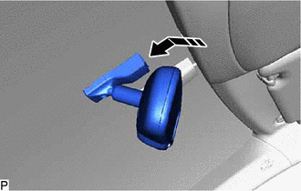
1. INSTALL INNER REAR VIEW MIRROR ASSEMBLY (w/o Pre-collision System)
(a) Install the inner rear view mirror assembly as shown in the illustration.
.png) |
Install in this Direction |
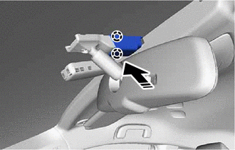
(b) Using a T20 "TORX" socket wrench, install the screw.
Torque:
1.8 N·m {18 kgf·cm, 16 in·lbf}
(c) Connect the connector.
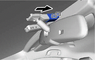
2. INSTALL INNER REAR VIEW MIRROR STAY HOLDER COVER (w/o Pre-collision System)
(a) Engage the claws to install the inner rear view mirror stay holder cover as shown in the illustration.
|
|
Install in this Direction |
|
(b) Slide the inner rear view mirror stay holder cover to engage the guides. |
|
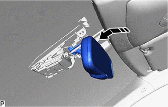
3. INSTALL INNER REAR VIEW MIRROR ASSEMBLY (w/ Pre-collision System)
(a) Install the inner rear view mirror assembly as shown in the illustration.
|
|
Install in this Direction |
|
(b) Using a T20 "TORX" socket wrench, install the screw. Torque: 1.8 N·m {18 kgf·cm, 16 in·lbf} |
|
.png)
(c) Engage the clamp.
(d) Connect the connector.
4. INSTALL NO. 1 FORWARD RECOGNITION COVER (w/ Pre-collision System)
Click here .gif)
5. INSTALL NO. 2 FORWARD RECOGNITION COVER (w/ Pre-collision System)
Click here
 Removal
REMOVAL
PROCEDURE
1. REMOVE INNER REAR VIEW MIRROR STAY HOLDER COVER (w/o Pre-collision System)
(a) Disengage the guides to slide the inner rear view mirror stay holder
cover.
...

Other materials:
Toyota CH-R Service Manual > Lumbar Switch: Inspection
INSPECTION
PROCEDURE
1. INSPECT FRONT LUMBAR POWER SEAT SWITCH
(a) Check the resistance.
(1) Measure the resistance according to the value(s) in the table below.
Standard Resistance:
Tester Connection
Condition
Specified Condit ...
Toyota CH-R Service Manual > Audio And Visual System(for Radio And Display Type): Black Screen
PROCEDURE
1.
CHECK DISPLAY SETTING
(a) Check that the display is not in screen off mode.
OK:
The display setting is not in screen off mode.
NG
CHANGE SCREEN TO SCREEN ON MODE
OK
...
Toyota C-HR (AX20) 2023-2026 Owner's Manual
Toyota CH-R Owners Manual
- For safety and security
- Instrument cluster
- Operation of each component
- Driving
- Interior features
- Maintenance and care
- When trouble arises
- Vehicle specifications
- For owners
Toyota CH-R Service Manual
- Introduction
- Maintenance
- Audio / Video
- Cellular Communication
- Navigation / Multi Info Display
- Park Assist / Monitoring
- Brake (front)
- Brake (rear)
- Brake Control / Dynamic Control Systems
- Brake System (other)
- Parking Brake
- Axle And Differential
- Drive Shaft / Propeller Shaft
- K114 Cvt
- 3zr-fae Battery / Charging
- Networking
- Power Distribution
- Power Assist Systems
- Steering Column
- Steering Gear / Linkage
- Alignment / Handling Diagnosis
- Front Suspension
- Rear Suspension
- Tire / Wheel
- Tire Pressure Monitoring
- Door / Hatch
- Exterior Panels / Trim
- Horn
- Lighting (ext)
- Mirror (ext)
- Window / Glass
- Wiper / Washer
- Door Lock
- Heating / Air Conditioning
- Interior Panels / Trim
- Lighting (int)
- Meter / Gauge / Display
- Mirror (int)
- Power Outlets (int)
- Pre-collision
- Seat
- Seat Belt
- Supplemental Restraint Systems
- Theft Deterrent / Keyless Entry

0.0069