Toyota CH-R Service Manual: Removal
REMOVAL
PROCEDURE
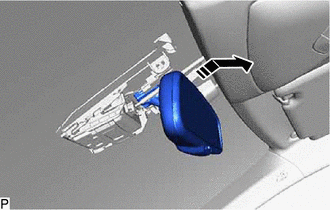
1. REMOVE INNER REAR VIEW MIRROR STAY HOLDER COVER (w/o Pre-collision System)
|
(a) Disengage the guides to slide the inner rear view mirror stay holder cover. |
|
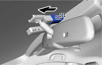
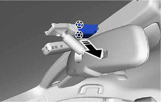
(b) Disengage the claws to remove the inner rear view mirror stay holder cover as shown in the illustration.
.png) |
Remove in this Direction |
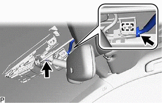
2. REMOVE INNER REAR VIEW MIRROR ASSEMBLY (w/o Pre-collision System)
|
(a) Disconnect the connector. |
|
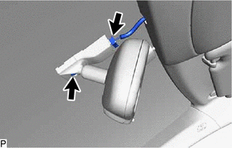
(b) Using a T20 "TORX" socket wrench, remove the screw.
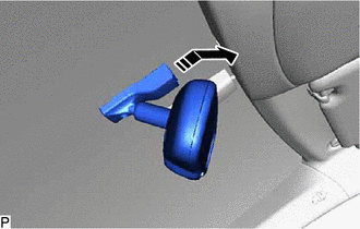
(c) Remove the inner rear view mirror assembly as shown in the illustration.
|
|
Remove in this Direction |
3. REMOVE NO. 2 FORWARD RECOGNITION COVER (w/ Pre-collision System)
Click here .gif)
4. REMOVE NO. 1 FORWARD RECOGNITION COVER (w/ Pre-collision System)
Click here
5. REMOVE INNER REAR VIEW MIRROR ASSEMBLY (w/ Pre-collision System)
|
(a) Disconnect the connector. |
|
(b) Disengage the clamp.
(c) Using a T20 "TORX" socket wrench, remove the screw.
(d) Remove the inner rear view mirror assembly as shown in the illustration.
|
|
Remove in this Direction |
 Inspection
INSPECTION
PROCEDURE
1. INSPECT INNER REAR VIEW MIRROR ASSEMBLY
(a) Inspect the operation of the electrochromic inner rear view mirror assembly.
*a
Black Colored Tape
...
 Installation
INSTALLATION
PROCEDURE
1. INSTALL INNER REAR VIEW MIRROR ASSEMBLY (w/o Pre-collision System)
(a) Install the inner rear view mirror assembly as shown in the illustration.
Ins ...
Other materials:
Toyota CH-R Service Manual > Wireless Door Lock Control System(w/ Smart Key System): Problem Symptoms Table
PROBLEM SYMPTOMS TABLE
HINT:
Use the table below to help determine the cause of problem symptoms.
If multiple suspected areas are listed, the potential causes of the symptoms
are listed in order of probability in the "Suspected Area" column of the
table. Check each sy ...
Toyota CH-R Service Manual > Automatic High Beam System: Problem Symptoms Table
PROBLEM SYMPTOMS TABLE
NOTICE:
Before replacing the main body ECU (multiplex network body ECU), refer
to registration.*1
*1: w/ Smart Key System
When replacing the forward recognition camera, always replace it with
a new one. If a forward recognition camera which was inst ...
Toyota C-HR (AX20) 2023-2026 Owner's Manual
Toyota CH-R Owners Manual
- For safety and security
- Instrument cluster
- Operation of each component
- Driving
- Interior features
- Maintenance and care
- When trouble arises
- Vehicle specifications
- For owners
Toyota CH-R Service Manual
- Introduction
- Maintenance
- Audio / Video
- Cellular Communication
- Navigation / Multi Info Display
- Park Assist / Monitoring
- Brake (front)
- Brake (rear)
- Brake Control / Dynamic Control Systems
- Brake System (other)
- Parking Brake
- Axle And Differential
- Drive Shaft / Propeller Shaft
- K114 Cvt
- 3zr-fae Battery / Charging
- Networking
- Power Distribution
- Power Assist Systems
- Steering Column
- Steering Gear / Linkage
- Alignment / Handling Diagnosis
- Front Suspension
- Rear Suspension
- Tire / Wheel
- Tire Pressure Monitoring
- Door / Hatch
- Exterior Panels / Trim
- Horn
- Lighting (ext)
- Mirror (ext)
- Window / Glass
- Wiper / Washer
- Door Lock
- Heating / Air Conditioning
- Interior Panels / Trim
- Lighting (int)
- Meter / Gauge / Display
- Mirror (int)
- Power Outlets (int)
- Pre-collision
- Seat
- Seat Belt
- Supplemental Restraint Systems
- Theft Deterrent / Keyless Entry

0.047