Toyota CH-R Service Manual: Installation
INSTALLATION
CAUTION / NOTICE / HINT
HINT:
- Use the same procedure for the RH side and LH side.
- The following procedure is for the LH side.
PROCEDURE
1. INSTALL FRONT AXLE HUB SUB-ASSEMBLY
(a) Secure the steering knuckle between aluminum plates in a vise.
NOTICE:
Do not overtighten the vise.
(b) Install the front axle hub sub-assembly and front disc brake dust cover to the steering knuckle with the 3 bolts.
Torque:
130 N·m {1326 kgf·cm, 96 ft·lbf}
NOTICE:
- Be careful not to damage the speed sensor rotor or contact surfaces.
- Do not allow foreign matter to contact the speed sensor rotor or contact surfaces.
2. INSTALL FRONT AXLE ASSEMBLY
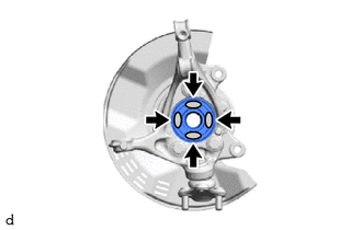
(a) Apply 0.1 to 0.3 g (0.00353 to 0.0105 oz) of Toyota Body Grease W to each of the 4 areas shown in the illustration.
.png) |
Toyota Body Grease W |
(b) Install the front axle assembly to the front shock absorber assembly with the 2 bolts and 2 nuts.
Torque:
270 N·m {2753 kgf·cm, 199 ft·lbf}
NOTICE:
- Do not apply lubricants to the steering knuckle and shock absorber contact surfaces.
- When installing the nuts, keep the bolts from rotating.
HINT:
The bolts can be installed in either direction, however, make sure that they are both installed in the same direction.
3. INSTALL FRONT DRIVE SHAFT ASSEMBLY
|
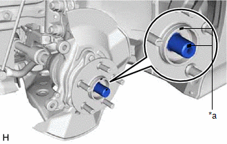
(a) Align the matchmarks on the front drive shaft assembly and front axle hub sub-assembly, and connect the front drive shaft assembly to the front axle assembly. NOTICE:
|
|
4. CONNECT FRONT LOWER NO. 1 SUSPENSION ARM SUB-ASSEMBLY
(a) Connect the front lower No. 1 suspension arm sub-assembly to the front lower ball joint assembly with the bolt and 2 nuts.
Torque:
89 N·m {908 kgf·cm, 66 ft·lbf}
5. CONNECT TIE ROD END SUB-ASSEMBLY
Click here
.gif)
6. INSTALL FRONT DISC
Click here
7. INSTALL FRONT DISC BRAKE CALIPER ASSEMBLY
Click here
8. INSTALL FRONT AXLE SHAFT NUT
(a) Clean the threaded parts on the front drive shaft assembly and a new front axle shaft nut using non-residue solvent.
NOTICE:
- Be sure to perform this work even when using a new front drive shaft assembly.
- Keep the threaded parts free of oil and foreign matter.
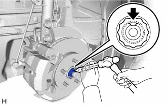
(b) Using a 30 mm deep socket wrench, while applying the brakes, temporarily install the front axle shaft nut.
Torque:
216 N·m {2203 kgf·cm, 159 ft·lbf}
NOTICE:
Stake the front axle shaft nut after inspecting for looseness and runout in the following steps.
HINT:
Keep depressing the brake pedal to prevent the front drive shaft from rotating.
9. SEPARATE FRONT DISC BRAKE CALIPER ASSEMBLY
Click here
10. REMOVE FRONT DISC
Click here
11. INSPECT FRONT AXLE HUB BEARING LOOSENESS
Click here
12. INSPECT FRONT AXLE HUB RUNOUT
Click here
13. INSTALL FRONT DISC
Click here
14. INSTALL FRONT DISC BRAKE CALIPER ASSEMBLY
Click here
15. INSTALL FRONT SPEED SENSOR
|
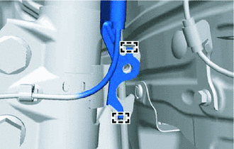
(a) Set the 2 hooks of front speed sensor to the front shock absorber assembly. NOTICE: Do not twist the front speed sensor when installing it. |
|
(b) Install the front speed sensor and front flexible hose to the front shock absorber assembly with the bolt.
Torque:
29 N·m {296 kgf·cm, 21 ft·lbf}
NOTICE:
Do not twist the front flexible hose when installing it.
(c) Install the front speed sensor to the steering knuckle with the bolt.
Torque:
8.5 N·m {87 kgf·cm, 75 in·lbf}
NOTICE:
- Prevent foreign matter from attaching to the front speed sensor tip.
- Firmly insert the front speed sensor body into the steering knuckle before tightening the bolt.
- After installing the front speed sensor to the steering knuckle, make sure that there is no clearance between the front speed sensor stay and steering knuckle. Also make sure that no foreign matter is stuck between the parts.
- Do not twist the front speed sensor when installing it.
(d) Engage the clamp.
NOTICE:
Do not twist the front speed sensor when installing it.
16. STAKE FRONT AXLE SHAFT NUT
|
(a) Using a chisel and hammer, stake the front axle shaft nut. |
|
17. INSTALL FRONT WHEEL
Click here
18. INSPECT AND ADJUST FRONT WHEEL ALIGNMENT
Click here
19. CHECK FOR SPEED SENSOR SIGNAL
Click here
 On-vehicle Inspection
ON-VEHICLE INSPECTION
CAUTION / NOTICE / HINT
HINT:
Use the same procedure for the RH side and LH side.
The following procedure is for the LH side.
PROCEDURE
1. REMOVE FRONT WHE ...
 Removal
REMOVAL
CAUTION / NOTICE / HINT
The necessary procedures (adjustment, calibration, initialization, or registration)
that must be performed after parts are removed and installed, or replaced during ...
Other materials:
Toyota CH-R Service Manual > Hood Lock Control Cable Assembly: Installation
INSTALLATION
PROCEDURE
1. INSTALL HOOD LOCK CONTROL CABLE ASSEMBLY
(a) Pass the hood lock control cable assembly into the engine compartment.
(b) Engage the grommet.
*a
Grommet
-
-
(c) Connect the hood lock control cable assembly to the cl ...
Toyota CH-R Service Manual > Navigation System: AV Signal Stoppage (Low Battery Voltage) (B158F)
DESCRIPTION
This DTC is stored when a video or audio signal is interrupted due to battery
voltage input to the radio and display receiver assembly dropping temporarily.
DTC No.
Detection Item
DTC Detection Condition
Trouble Area
B158F
...
Toyota C-HR (AX20) 2023-2026 Owner's Manual
Toyota CH-R Owners Manual
- For safety and security
- Instrument cluster
- Operation of each component
- Driving
- Interior features
- Maintenance and care
- When trouble arises
- Vehicle specifications
- For owners
Toyota CH-R Service Manual
- Introduction
- Maintenance
- Audio / Video
- Cellular Communication
- Navigation / Multi Info Display
- Park Assist / Monitoring
- Brake (front)
- Brake (rear)
- Brake Control / Dynamic Control Systems
- Brake System (other)
- Parking Brake
- Axle And Differential
- Drive Shaft / Propeller Shaft
- K114 Cvt
- 3zr-fae Battery / Charging
- Networking
- Power Distribution
- Power Assist Systems
- Steering Column
- Steering Gear / Linkage
- Alignment / Handling Diagnosis
- Front Suspension
- Rear Suspension
- Tire / Wheel
- Tire Pressure Monitoring
- Door / Hatch
- Exterior Panels / Trim
- Horn
- Lighting (ext)
- Mirror (ext)
- Window / Glass
- Wiper / Washer
- Door Lock
- Heating / Air Conditioning
- Interior Panels / Trim
- Lighting (int)
- Meter / Gauge / Display
- Mirror (int)
- Power Outlets (int)
- Pre-collision
- Seat
- Seat Belt
- Supplemental Restraint Systems
- Theft Deterrent / Keyless Entry

0.0068