Toyota CH-R Service Manual: Removal
REMOVAL
CAUTION / NOTICE / HINT
The necessary procedures (adjustment, calibration, initialization, or registration) that must be performed after parts are removed and installed, or replaced during front axle hub sub-assembly removal/installation are shown below.
Necessary Procedures After Parts Removed/Installed/Replaced|
Replaced Part or Performed Procedure |
Necessary Procedure |
Effect/Inoperative Function when Necessary Procedure not Performed |
Link |
|---|---|---|---|
|
Front wheel alignment adjustment |
|
|
|
HINT:
- Use the same procedure for the RH side and LH side.
- The following procedure is for the LH side.
PROCEDURE
1. REMOVE FRONT WHEEL
Click here
.gif)
2. REMOVE FRONT AXLE SHAFT NUT
Click here
3. SEPARATE FRONT SPEED SENSOR
|
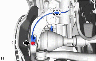
(a) Remove the bolt and separate the front speed sensor and front flexible hose from the front shock absorber assembly. NOTICE: Be sure to separate the front speed sensor and front flexible hose from the front shock absorber assembly completely. |
|
.png)
|
(b) Remove the bolt, disengage the clamp and separate the front speed sensor from the front shock absorber assembly and steering knuckle. NOTICE:
|
|
4. SEPARATE TIE ROD END SUB-ASSEMBLY
Click here
5. SEPARATE FRONT DISC BRAKE CALIPER ASSEMBLY
Click here
6. REMOVE FRONT DISC
Click here
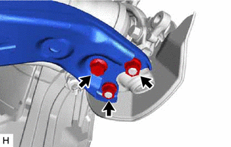
7. SEPARATE FRONT LOWER NO. 1 SUSPENSION ARM SUB-ASSEMBLY
|
(a) Remove the bolt and 2 nuts and separate the front lower No. 1 suspension arm sub-assembly from the front lower ball joint assembly. |
|
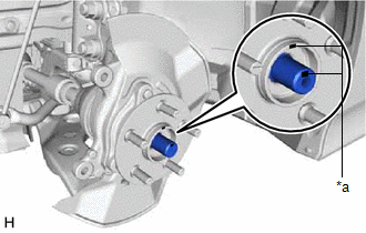
8. SEPARATE FRONT DRIVE SHAFT ASSEMBLY
|
(a) Put matchmarks on the front drive shaft assembly and the front axle hub sub-assembly. |
|
|
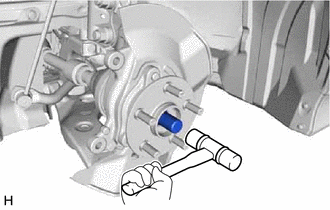
(b) Using a plastic hammer, separate the front drive shaft assembly from the front axle assembly. NOTICE:
HINT: If it is difficult to separate the front drive shaft assembly from the front axle assembly, tap the end of the front drive shaft assembly using a brass bar and a hammer. |
|
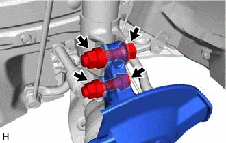
9. REMOVE FRONT AXLE ASSEMBLY
|
(a) Remove the 2 bolts, 2 nuts and front axle assembly from the front shock absorber assembly. NOTICE: When removing the nuts, keep the bolts from rotating. |
|
10. REMOVE FRONT AXLE HUB SUB-ASSEMBLY
|
(a) Secure the front axle assembly between aluminum plates in a vise. NOTICE: Do not overtighten the vise. |
|
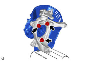
(b) Remove the 3 bolts, front axle hub sub-assembly and front disc brake dust cover from the steering knuckle.
NOTICE:
- Do not drop the front axle hub sub-assembly.
- Be careful not to damage the speed sensor rotor or contact surfaces.
- Do not allow foreign matter to contact the speed sensor rotor or contact surfaces.
 Installation
INSTALLATION
CAUTION / NOTICE / HINT
HINT:
Use the same procedure for the RH side and LH side.
The following procedure is for the LH side.
PROCEDURE
1. INSTALL FRONT AXLE HUB SU ...
 Front Axle Hub Bolt
Components
COMPONENTS
ILLUSTRATION
*1
FRONT AXLE HUB BOLT
*2
FRONT DISC
*3
FRONT DISC BRAKE CALIPER ASSEMBLY
- ...
Other materials:
Toyota CH-R Service Manual > Front Evaporator Temperature Sensor(for Denso Made): Removal
REMOVAL
CAUTION / NOTICE / HINT
The necessary procedures (adjustment, calibration, initialization, or registration)
that must be performed after parts are removed, installed, or replaced during the
No. 1 cooler thermistor removal/installation are shown below.
Necessary Procedure After Parts R ...
Toyota CH-R Service Manual > Blower Unit(for Denso Made): Disassembly
DISASSEMBLY
PROCEDURE
1. PRECAUTION
NOTICE:
Make sure to perform initialization after replacing the No. 1 blower damper servo
sub-assembly. If initialization is not performed, the air conditioner unit assembly
will not perform properly as the air conditioning amplifier assembly will not be
...
Toyota C-HR (AX20) 2023-2026 Owner's Manual
Toyota CH-R Owners Manual
- For safety and security
- Instrument cluster
- Operation of each component
- Driving
- Interior features
- Maintenance and care
- When trouble arises
- Vehicle specifications
- For owners
Toyota CH-R Service Manual
- Introduction
- Maintenance
- Audio / Video
- Cellular Communication
- Navigation / Multi Info Display
- Park Assist / Monitoring
- Brake (front)
- Brake (rear)
- Brake Control / Dynamic Control Systems
- Brake System (other)
- Parking Brake
- Axle And Differential
- Drive Shaft / Propeller Shaft
- K114 Cvt
- 3zr-fae Battery / Charging
- Networking
- Power Distribution
- Power Assist Systems
- Steering Column
- Steering Gear / Linkage
- Alignment / Handling Diagnosis
- Front Suspension
- Rear Suspension
- Tire / Wheel
- Tire Pressure Monitoring
- Door / Hatch
- Exterior Panels / Trim
- Horn
- Lighting (ext)
- Mirror (ext)
- Window / Glass
- Wiper / Washer
- Door Lock
- Heating / Air Conditioning
- Interior Panels / Trim
- Lighting (int)
- Meter / Gauge / Display
- Mirror (int)
- Power Outlets (int)
- Pre-collision
- Seat
- Seat Belt
- Supplemental Restraint Systems
- Theft Deterrent / Keyless Entry

0.0076