Toyota CH-R Service Manual: Front Axle Hub Bolt
Components
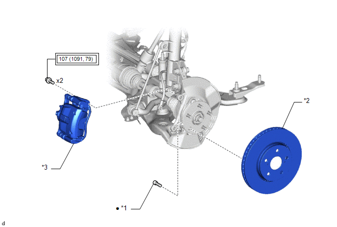
COMPONENTS
ILLUSTRATION
|
*1 |
FRONT AXLE HUB BOLT |
*2 |
FRONT DISC |
|
*3 |
FRONT DISC BRAKE CALIPER ASSEMBLY |
- |
- |
.png) |
Tightening torque for "Major areas involving basic vehicle performance such as moving/turning/stopping" : N*m (kgf*cm, ft.*lbf) |
● |
Non-reusable part |
Replacement
REPLACEMENT
CAUTION / NOTICE / HINT
HINT:
- Use the same procedure for the RH side and LH side.
- The following procedure is for the LH side.
PROCEDURE
1. REMOVE FRONT WHEEL
Click here
.gif)
2. SEPARATE FRONT DISC BRAKE CALIPER ASSEMBLY
(a) Remove the 2 bolts and separate the front disc brake caliper assembly from the steering knuckle.
NOTICE:
Use wire or an equivalent tool to keep the front disc brake caliper assembly from hanging by the front flexible hose.
3. REMOVE FRONT DISC
Click here
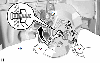
4. REMOVE FRONT AXLE HUB BOLT
|
(a) Temporarily install 2 service nuts to the front axle hub bolts as shown in the illustration. Recommended Service Nut: Thread diameter: 12.0 mm (0.472 in.) Thread pitch: 1.5 mm (0.0591 in.) NOTICE: Install the service nuts to prevent damage to the front axle hub bolts. |
|
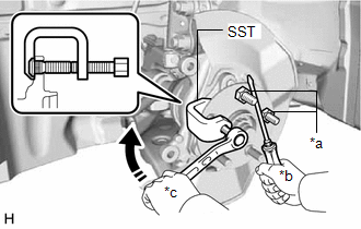
(b) Using SST and a screwdriver or an equivalent tool to hold the front axle hub sub-assembly, remove the front axle hub bolt.
SST: 09611-12010
NOTICE:
Do not damage the threads of the front axle hub bolts.
5. INSTALL FRONT AXLE HUB BOLT
(a) Temporarily install a new front axle hub bolt to the front axle hub sub-assembly.
|
(b) Install a washer and service nut to the front axle hub bolt as shown in the illustration. Recommended Service Nut: Thread diameter: 12.0 mm (0.472 in.) Thread pitch: 1.5 mm (0.0591 in.) HINT: Recommended washer thickness is 5 mm (0.197 in.) or more. |
|
(c) Using a screwdriver or an equivalent tool to hold the front axle hub sub-assembly, install the front axle hub bolt by tightening the service nut.
NOTICE:
- Install the service nuts to prevent damage to the front axle hub bolts.
- Do not damage the threads of the front axle hub bolts.
(d) Remove the 3 service nuts and washer from the 3 front axle hub bolts.
6. INSTALL FRONT DISC
Click here
7. INSTALL FRONT DISC BRAKE CALIPER ASSEMBLY
(a) Install the front disc brake caliper assembly to the steering knuckle with the 2 bolts.
Torque:
107 N·m {1091 kgf·cm, 79 ft·lbf}
NOTICE:
- Do not twist the front flexible hose when installing the front disc brake caliper assembly.
- Make sure that there is no foreign matter on the threads of the bolt.
8. INSTALL FRONT WHEEL
Click here
 Removal
REMOVAL
CAUTION / NOTICE / HINT
The necessary procedures (adjustment, calibration, initialization, or registration)
that must be performed after parts are removed and installed, or replaced during ...

Other materials:
Toyota CH-R Service Manual > Seat Heater System: Problem Symptoms Table
PROBLEM SYMPTOMS TABLE
NOTICE:
If the battery voltage is low, the seat heater system may not operate. Refer
to Data List for power steering system.
Click here
HINT:
Use the table below to help determine the cause of problem symptoms.
If multiple suspected areas are listed, the p ...
Toyota CH-R Service Manual > Power Mirror Control System: Problem Symptoms Table
PROBLEM SYMPTOMS TABLE
NOTICE:
If the battery voltage is low, the mirror heater function may not operate. In
this case, check the Data List item "Battery Control Count (Body ECU)".
Click here
HINT:
Use the table below to help determine the cause of problem symptoms.
...
Toyota C-HR (AX20) 2023-2026 Owner's Manual
Toyota CH-R Owners Manual
- For safety and security
- Instrument cluster
- Operation of each component
- Driving
- Interior features
- Maintenance and care
- When trouble arises
- Vehicle specifications
- For owners
Toyota CH-R Service Manual
- Introduction
- Maintenance
- Audio / Video
- Cellular Communication
- Navigation / Multi Info Display
- Park Assist / Monitoring
- Brake (front)
- Brake (rear)
- Brake Control / Dynamic Control Systems
- Brake System (other)
- Parking Brake
- Axle And Differential
- Drive Shaft / Propeller Shaft
- K114 Cvt
- 3zr-fae Battery / Charging
- Networking
- Power Distribution
- Power Assist Systems
- Steering Column
- Steering Gear / Linkage
- Alignment / Handling Diagnosis
- Front Suspension
- Rear Suspension
- Tire / Wheel
- Tire Pressure Monitoring
- Door / Hatch
- Exterior Panels / Trim
- Horn
- Lighting (ext)
- Mirror (ext)
- Window / Glass
- Wiper / Washer
- Door Lock
- Heating / Air Conditioning
- Interior Panels / Trim
- Lighting (int)
- Meter / Gauge / Display
- Mirror (int)
- Power Outlets (int)
- Pre-collision
- Seat
- Seat Belt
- Supplemental Restraint Systems
- Theft Deterrent / Keyless Entry

0.0073