Toyota CH-R Service Manual: Installation
INSTALLATION
CAUTION / NOTICE / HINT
PROCEDURE
1. INSTALL BRAKE ACTUATOR BRACKET CUSHION
(a) Install the brake actuator bracket cushion to the brake actuator bracket assembly.
2. INSTALL NO. 1 BRAKE ACTUATOR CASE COLLAR
(a) Install the No. 1 brake actuator case collar to the brake actuator bracket cushion.
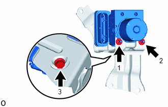
3. INSTALL BRAKE ACTUATOR ASSEMBLY
(a) Temporarily install the brake actuator assembly with the 2 nuts and bolt.
|
(b) Fully tighten the 2 nuts and bolt in the order shown in the illustration. Torque: 6.5 N·m {66 kgf·cm, 58 in·lbf} NOTICE:
|
|
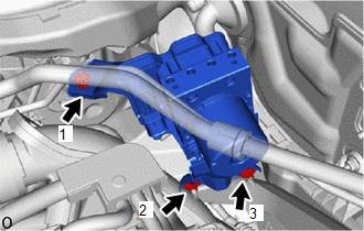
4. INSTALL BRAKE ACTUATOR WITH BRACKET
(a) Temporarily install the brake actuator with bracket to the vehicle body with the bolt and 2 nuts.
|
(b) Fully tighten the bolt and 2 nuts in the order shown in the illustration. Torque: 19 N·m {194 kgf·cm, 14 ft·lbf} NOTICE: Do not damage the brake tubes. |
|
|
(c) Temporarily tighten each brake line to the correct position on the brake actuator assembly as shown in the illustration. |
|
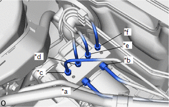
|
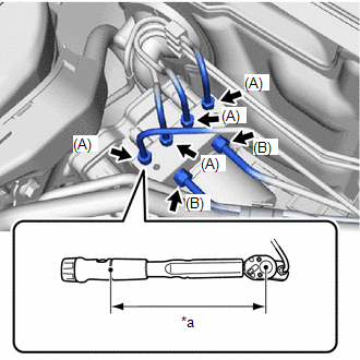
(d) Using a 10 mm and 12 mm union nut wrench, connect the 6 brake tubes to the brake actuator assembly. Torque: Specified tightening torque (A) : 15.2 N·m {155 kgf·cm, 11 ft·lbf} Specified tightening torque (B) : 19.5 N·m {199 kgf·cm, 14 ft·lbf} NOTICE:
HINT:
|
|
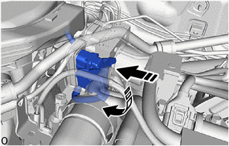
(e) Connect the connector to the brake actuator assembly and lock the lock lever.
NOTICE:
- Make sure that the actuator connector can be connected smoothly. Do not allow water, oil or dirt to enter the connector.
- Make sure that the connector is locked securely.
.png) |
Connect the connector |
.png) |
Lock the lock lever |
5. INSTALL OUTER COWL TOP PANEL SUB-ASSEMBLY
Click here
.gif)
6. INSTALL BATTERY
Click here
7. INSTALL COWL BODY MOUNTING REINFORCEMENT RH
Click here
8. INSTALL COWL BODY MOUNTING REINFORCEMENT LH
Click here
9. INSTALL WATER GUARD PLATE LH
Click here
10. INSTALL NO. 1 HEATER AIR DUCT SPLASH SHIELD SEAL
Click here
11. INSTALL WINDSHIELD WIPER MOTOR AND LINK ASSEMBLY
Click here
12. CONNECT CABLE TO NEGATIVE BATTERY TERMINAL
Click here
NOTICE:
When disconnecting the cable, some systems need to be initialized after the cable is reconnected.
Click here
13. BLEED BRAKE SYSTEM
Click here
14. INSPECT BRAKE ACTUATOR USING TECHSTREAM
Click here
15. PERFORM SYSTEM VARIANT LEARNING
Click here
16. CHECK FOR AND CLEAR DTCS
Click here
 On-vehicle Inspection
ON-VEHICLE INSPECTION
CAUTION / NOTICE / HINT
PROCEDURE
1. CONNECT TECHSTREAM
(a) Connect the Techstream to the DLC3 with the ignition switch off.
(b) Start the engine and run it at idle.
(c) Tu ...
 Removal
REMOVAL
CAUTION / NOTICE / HINT
The necessary procedures (adjustment, calibration, initialization, or registration)
that must be performed after parts are removed, installed, or replaced during th ...
Other materials:
Toyota CH-R Service Manual > Lin Communication System: LIN Communication Bus Malfunction (B2325)
DESCRIPTION
If the main body ECU (multiplex network body ECU) detects a communication error
with an ECU connected to the door bus lines for 7 seconds or more, DTC B2325 will
be stored.
DTC No.
Detection Item
DTC Detection Condition
Trouble Area
...
Toyota CH-R Service Manual > 3zr-fae Oil And Oil Filter: Components
COMPONENTS
ILLUSTRATION
*A
for Oil Filter Sub-assembly Type
*B
for Oil Filter Element Kit Type
*1
CENTER NO. 4 ENGINE UNDER COVER
*2
OIL FILTER CAP ASSEMBLY
*3
OIL FILLER CAP ...
Toyota C-HR (AX20) 2023-2026 Owner's Manual
Toyota CH-R Owners Manual
- For safety and security
- Instrument cluster
- Operation of each component
- Driving
- Interior features
- Maintenance and care
- When trouble arises
- Vehicle specifications
- For owners
Toyota CH-R Service Manual
- Introduction
- Maintenance
- Audio / Video
- Cellular Communication
- Navigation / Multi Info Display
- Park Assist / Monitoring
- Brake (front)
- Brake (rear)
- Brake Control / Dynamic Control Systems
- Brake System (other)
- Parking Brake
- Axle And Differential
- Drive Shaft / Propeller Shaft
- K114 Cvt
- 3zr-fae Battery / Charging
- Networking
- Power Distribution
- Power Assist Systems
- Steering Column
- Steering Gear / Linkage
- Alignment / Handling Diagnosis
- Front Suspension
- Rear Suspension
- Tire / Wheel
- Tire Pressure Monitoring
- Door / Hatch
- Exterior Panels / Trim
- Horn
- Lighting (ext)
- Mirror (ext)
- Window / Glass
- Wiper / Washer
- Door Lock
- Heating / Air Conditioning
- Interior Panels / Trim
- Lighting (int)
- Meter / Gauge / Display
- Mirror (int)
- Power Outlets (int)
- Pre-collision
- Seat
- Seat Belt
- Supplemental Restraint Systems
- Theft Deterrent / Keyless Entry

0.0138