Toyota CH-R Service Manual: Terminals Of Ecu
TERMINALS OF ECU
CHECK TIRE PRESSURE WARNING ECU AND RECEIVER
(a) Disconnect the M23 tire pressure warning ECU and receiver connector and measure the voltage or resistance on the wire harness side.
|
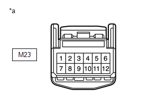
*a |
Front view of wire harness connector (to Tire Pressure Warning ECU and Receiver) |
|
Terminal No. (Symbol) |
Wiring Color |
Terminal Description |
Condition |
Specified Condition |
|---|---|---|---|---|
|
M23-1 (IG) - M23-12 (GND) |
SB - W-B |
IG power source |
Ignition switch to ON |
10 to 16 V |
|
M23-7 (+B) - M23-12 (GND) |
R - W-B (*1) B - W-B (*2) |
Power supply (from battery) |
Always |
10 to 16 V |
|
M23-12 (GND) - Body ground |
W-B - Body ground |
Ground |
Always |
Below 1 Ω |
- *1: w/o Smart Key System
- *2: w/ Smart Key System
(b) Connect the M23 tire pressure warning ECU and receiver connector.
(c) Measure the voltage and resistance according to the value(s) in the table below. If the result is not as specified, the ECU may be malfunctioning.
HINT:
Measure the values on the wire harness side while the connector is connected.
|
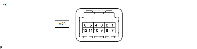
*a |
Component with harness connected (Tire Pressure Warning ECU and Receiver) |
- |
- |
|
Terminal No. (Symbol) |
Wiring Color |
Terminal Description |
Condition |
Specified Condition |
|---|---|---|---|---|
|
M23-3 (CLSW) - M23-12 (GND) |
Y - W-B |
Tire pressure warning reset switch |
|
Below 1.5 V |
|
8 to 15 V |
|||
|
M23-4 (RDA) - M23-12 (GND) |
G - W-B |
Output signals |
Ignition switch to ON |
Pulse generation (see waveform 1) |
|
M23-5 (PRG) - M23-12 (GND) |
W - W-B |
Input signals |
Ignition switch to ON |
Pulse generation (see waveform 1) |
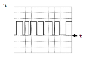
(d) Using an oscilloscope, check waveform 1.
|
*a |
Example |
|
*b |
GND |
|
Item |
Contents |
|---|---|
|
Terminal |
M23-4 (RDA) - M23-12 (GND) M23-5 (PRG) - M23-12 (GND) |
|
Tool setting |
5 V/DIV, 5 ms./DIV. |
|
Vehicle condition |
Ignition switch to ON |
HINT:
The waveform shown in the illustration is an example. If the tester displays a waveform that alternates between high and low, where high is a voltage that is between the IG power source voltage and a voltage 2.2 V lower than the IG power source voltage, and where low is a voltage of between 0 and 1.2 V, the ECU can be judged normal.
 Problem Symptoms Table
PROBLEM SYMPTOMS TABLE
HINT:
Use the table below to help determine the cause of problem symptoms.
If multiple suspected areas are listed, the potential causes of the symptoms
are lis ...
 Diagnosis System
DIAGNOSIS SYSTEM
CHECK WARNING LIGHT
NOTICE:
When there is a problem with the tire pressure warning system, the tire
pressure warning light blinks at 0.5 second intervals, and illuminat ...
Other materials:
Toyota CH-R Service Manual > Front Seatback Heater: Removal
REMOVAL
CAUTION / NOTICE / HINT
The necessary procedures (adjustment, calibration, initialization, or registration)
that must be performed after parts are removed, installed, or replaced during the
front seatback heater assembly removal/installation are shown below.
Necessary Procedure After ...
Toyota CH-R Service Manual > Fog Light Assembly: Installation
INSTALLATION
CAUTION / NOTICE / HINT
HINT:
Use the same procedure for the RH side and LH side.
The following procedure is for the LH side.
PROCEDURE
1. INSTALL FOG LIGHT ASSEMBLY
(a) Engage the guide to install the fog light assembly.
...
Toyota C-HR (AX20) 2023-2026 Owner's Manual
Toyota CH-R Owners Manual
- For safety and security
- Instrument cluster
- Operation of each component
- Driving
- Interior features
- Maintenance and care
- When trouble arises
- Vehicle specifications
- For owners
Toyota CH-R Service Manual
- Introduction
- Maintenance
- Audio / Video
- Cellular Communication
- Navigation / Multi Info Display
- Park Assist / Monitoring
- Brake (front)
- Brake (rear)
- Brake Control / Dynamic Control Systems
- Brake System (other)
- Parking Brake
- Axle And Differential
- Drive Shaft / Propeller Shaft
- K114 Cvt
- 3zr-fae Battery / Charging
- Networking
- Power Distribution
- Power Assist Systems
- Steering Column
- Steering Gear / Linkage
- Alignment / Handling Diagnosis
- Front Suspension
- Rear Suspension
- Tire / Wheel
- Tire Pressure Monitoring
- Door / Hatch
- Exterior Panels / Trim
- Horn
- Lighting (ext)
- Mirror (ext)
- Window / Glass
- Wiper / Washer
- Door Lock
- Heating / Air Conditioning
- Interior Panels / Trim
- Lighting (int)
- Meter / Gauge / Display
- Mirror (int)
- Power Outlets (int)
- Pre-collision
- Seat
- Seat Belt
- Supplemental Restraint Systems
- Theft Deterrent / Keyless Entry

0.0075