Toyota CH-R Service Manual: Fuel Receiver Gauge Display Malfunction
DESCRIPTION
OPERATION
The combination meter assembly uses the fuel injection volume signal from the ECM, fuel sender gauge assembly to detect the amount of fuel remaining in the fuel tank assembly. Each gauge assembly has a variable resistor whose resistance changes according to the amount of fuel remaining. The gauge assemblies receive voltage from the combination meter assembly and change the voltage based on the resistance that changes according to the amount of fuel remaining in the fuel tank assembly. The combination meter assembly receives a fuel injection volume signal from the ECM and detects the voltage between each variable resistor and each resistor in the combination meter assembly, and operates the fuel receiver gauge.
FUEL RECEIVER GAUGE READING
(a) During normal driving:
As the fuel level in the fuel tank assembly changes when driving on a hill or applying brakes, the fuel receiver gauge reading is updated according to the fuel injection volume during normal driving. However, as the fuel injection volume measurement has a margin of error, the value is indicated after correction by input values from the fuel sender gauge assembly.
(b) During refueling:
The fuel level in the fuel tank assembly rises rapidly when fuel is added. If the averaging process that is used during normal driving is used in this case, the fuel receiver gauge reading cannot be updated promptly. Therefore, when it is judged that fuel is being added to the vehicle based on the shift lever position and changes in the fuel level, output values from the fuel sender gauge assembly are immediately reflected in the fuel receiver gauge reading. This control is called refueling judgment.
REFUELING JUDGMENT CONDITIONS
NOTICE:
Add fuel with the ignition switch off to ensure safety and to enable refueling judgment so that an appropriate fuel receiver gauge reading is obtained. If it is necessary to add fuel with the ignition switch ON move the shift lever to P or N.
(a) Normal judgment condition (When normal refueling method is used)
With the ignition switch off, the fuel sender gauge assembly detects a change of 5.0 liters (5.3 US qts, 4.4 Imp. qts) or more in the fuel level.
(b) Other judgment conditions (When other refueling method is used)
Any of the following conditions is met:
- With the vehicle and engine stopped and the ignition switch ON the fuel sender gauge assembly detects a change of 5.0 liters (5.3 US qts, 4.4 Imp. qts) or more in the fuel level.
- With the vehicle stopped, the engine running, the ignition switch ON and the shift lever in P or N, the fuel sender gauge assembly detects a change of 5.0 liters (5.3 US qts, 4.4 Imp. qts) or more in the fuel level.
- With the vehicle stopped, the engine running, the ignition switch ON and the shift lever in any driving position, the fuel sender gauge assembly detects a change of 15.0 liters (15.9 US qts, 13.2 Imp. qts) or more in the fuel level.
PRECAUTION FOR REFUELING
The fuel sender gauge assembly cannot detect changes in the fuel level within certain ranges (around points E and F). Therefore, even if 5.0 liters (5.3 US qts, 4.4 Imp. qts) or more of fuel is added, refueling judgment may not be performed and the fuel receiver gauge reading may not change when fuel level is within such ranges.
FORCED RESET OF FUEL RECEIVER GAUGE
When driving at 1.8 km/h (1 mph) or more, if the output values from the fuel sender gauge assembly are different from the fuel receiver gauge reading by 15.0 liters (15.9 US qts, 13.2 Imp. qts) or more for approximately 2 minutes, output values from both gauge assemblies are immediately reflected in the fuel receiver gauge reading to compensate for a situation when refueling judgment cannot be made.
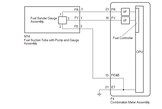
WIRING DIAGRAM
CAUTION / NOTICE / HINT
NOTICE:
When replacing the combination meter assembly, always replace it with a new one. If a combination meter assembly which was installed to another vehicle is used, the information stored in it will not match the information from the vehicle and a DTC may be stored.
HINT:
The fuel level warning light will come on when the fuel level is below 9.96 liters (10.5 US qts, 8.8 Imp. qts).
PROCEDURE
|
1. |
CHECK SYMPTOMS |
(a) Ask the customer about the problem symptoms.
|
Result |
Proceed to |
|---|---|
|
Malfunction occurs when adding fuel (Even after adding fuel, reading does not increase at all or increases very slowly, etc.) |
A |
|
Malfunction occurs during normal driving (The reading does not change, decreases quickly or decreases when the vehicle is not being driven, etc.) (The problem symptom recurs) |
B |
|
Malfunction occurs during normal driving (The reading does not change, decreases quickly or decreases when the vehicle is not being driven, etc.) (The problem symptom does not recur) |
C |
| B | .gif) |
GO TO STEP 10 |
| C | |
GO TO STEP 14 |
|
.gif)
|
2. |
CHECK FOR DTC |
(a) Check if SFI system DTCs are output.
- w/ Canister Pump Module:
Click here
.gif)
- w/o Canister Pump Module:
Click here
|
Result |
Proceed to |
|---|---|
|
SFI system DTCs are not output. |
A |
|
SFI system DTCs are output. (w/o Canister Pump Module) |
B |
|
SFI system DTCs are output. (w/ Canister Pump Module) |
C |
| B | |
GO TO SFI SYSTEM |
| C | |
GO TO SFI SYSTEM |
|
|
3. |
CHECK FOR DTC |
(a) Check if vehicle stability control system DTCs are output.
Click here
|
Result |
Proceed to |
|---|---|
|
Vehicle stability control system DTCs are not output. |
A |
|
Vehicle stability control system DTCs are output. |
B |
| B | |
GO TO VEHICLE STABILITY CONTROL SYSTEM |
|
|
4. |
CHECK FUEL RECEIVER GAUGE OPERATION BY ADDING FUEL |
(a) Record the fuel receiver gauge reading.
(b) If the fuel tank assembly is almost full, drain 20 liters or more of fuel. (This is not necessary when the fuel tank assembly is sufficiently below full.)
(c) Disconnect the cable from the negative (-) battery terminal to reset the fuel receiver gauge.
HINT:
Check that the ignition switch is turned off before disconnecting the cable from the negative (-) battery terminal.
(d) Connect the cable to the negative (-) battery terminal and turn the ignition switch ON.
(e) Check that the fuel receiver gauge has been reset.
(f) Drive the vehicle at 1.75 km/h (1 mph) or more, then move the shift lever to P and turn the ignition switch off.
(g) Add 5.0 liters or more of fuel, turn the ignition switch ON and check that the fuel receiver gauge reading increases in proportion to the amount of fuel added.
|
Result |
Proceed to |
|---|---|
|
Fuel receiver gauge reading increases in proportion to the amount of fuel added |
A |
|
Fuel receiver gauge reading does not change even when fuel is added |
B |
| B | |
GO TO STEP 6 |
|
|
5. |
INSPECT FUEL TANK ASSEMBLY |
HINT:
Inspect the fuel tank assembly for deformation, foreign matter or an improperly installed fuel receiver gauge, as this may be the cause of the fuel receiver gauge malfunction.
(a) Visually check the fuel tank assembly for any abnormalities.
(b) Check if there is an excessive amount of foreign matter in the fuel tank assembly.
(c) Check the installation condition of the fuel tank assembly, fuel sender gauge assembly.
|
Result |
Proceed to |
|---|---|
|
Normal |
A |
|
Appearance of the fuel tank assembly is abnormal. (w/o Canister Pump Module) |
B |
|
Appearance of the fuel tank assembly is abnormal. (w/ Canister Pump Module) |
C |
|
There is an excessive amount of foreign matter in the fuel tank assembly. |
D |
|
The fuel tank assembly, fuel sender gauge assembly is not installed correctly. |
E |
| B | |
REPLACE FUEL TANK ASSEMBLY |
| C | |
REPLACE FUEL TANK ASSEMBLY |
| D | |
CLEAN INSIDE OF FUEL TANK ASSEMBLY |
| E | |
INSTALL FUEL TANK ASSEMBLY OR FUEL SENDER GAUGE ASSEMBLY CORRECTLY |
|
|
6. |
READ VALUE USING TECHSTREAM (FUEL INPUT) |
(a) Connect the Techstream to the DLC3.
(b) Turn the ignition switch ON.
(c) Turn the Techstream on.
(d) Enter following menus: Body Electrical / Combination Meter / Data List.
(e) Read the Data List according to the display on the Techstream.
Body Electrical > Combination Meter > Data List|
Tester Display |
Measurement Item |
Range |
Normal Condition |
Diagnostic Note |
|---|---|---|---|---|
|
Fuel Input |
Fuel input |
Min.: 0 L, Max.: 127.5 L |
|
Unit :Liter |
|
Tester Display |
|---|
|
Fuel Input |
|
Result |
Proceed to |
|---|---|
|
Fuel level data displayed on the Techstream is almost the same as the fuel receiver gauge indication. |
A |
|
Fuel level data displayed on the Techstream differs from the fuel receiver gauge indication. |
B |
| B | |
REPLACE COMBINATION METER ASSEMBLY |
|
|
7. |
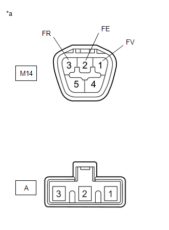
CHECK HARNESS AND CONNECTOR (COMBINATION METER ASSEMBLY - FUEL SUCTION TUBE WITH PUMP AND GAUGE ASSEMBLY) |
(a) Disconnect the F4 combination meter assembly connector.
(b) Disconnect the M14 fuel suction tube with pump and gauge assembly connector.
(c) Measure the resistance according to the value(s) in the table below.
Standard Resistance:
|
Tester Connection |
Condition |
Specified Condition |
|---|---|---|
|
M14-1 (FV) - F4-16 (FV) |
Always |
Below 1 Ω |
|
M14-2 (FE) - F4-15 (FE&B) |
Always |
Below 1 Ω |
|
M14-3 (FR) - F4-23 (FR) |
Always |
Below 1 Ω |
|
M14-1 (FV) - Body ground |
Always |
10 kΩ or higher |
|
M14-2 (FE) - Body ground |
Always |
10 kΩ or higher |
|
M14-3 (FR) - Body ground |
Always |
10 kΩ or higher |
| NG | |
REPAIR OR REPLACE HARNESS OR CONNECTOR |
|
|
8. |
INSPECT FUEL SUCTION TUBE WITH PUMP AND GAUGE ASSEMBLY |
(a) Remove the fuel suction tube with pump and gauge assembly.
- w/ Canister Pump Module: Click here
- w/o Canister Pump Module: Click here
|
(b) Measure the resistance according to the value(s) in the table below. Standard Resistance:
|
|
| NG | |
REPLACE FUEL SUCTION TUBE WITH PUMP AND GAUGE ASSEMBLY |
|
|
9. |
INSPECT FUEL SENDER GAUGE ASSEMBLY |
(a) Remove the fuel sender gauge assembly.
Click here
(b) Inspect the fuel sender gauge assembly.
Click here
| OK | |
REPLACE COMBINATION METER ASSEMBLY |
| NG | |
REPLACE FUEL SENDER GAUGE ASSEMBLY |
|
10. |
CHECK FOR DTC |
(a) Check if SFI system DTCs are output.
- w/ Canister Pump Module:
Click here
- w/o Canister Pump Module:
Click here
|
Result |
Proceed to |
|---|---|
|
SFI system DTCs are not output. |
A |
|
SFI system DTCs are output. (w/o Canister Pump Module) |
B |
|
SFI system DTCs are output. (w/ Canister Pump Module) |
C |
| B | |
GO TO SFI SYSTEM |
| C | |
GO TO SFI SYSTEM |
|
|
11. |
CHECK FOR DTC |
(a) Check if vehicle stability control system DTCs are output.
Click here
|
Result |
Proceed to |
|---|---|
|
Vehicle stability control system DTCs are not output. |
A |
|
Vehicle stability control system DTCs are output. |
B |
| B | |
GO TO VEHICLE STABILITY CONTROL SYSTEM |
|
|
12. |
CHECK FOR DTC |
(a) Check for DTCs.
Click here
|
Result |
Proceed to |
|---|---|
|
DTCs are not output. |
A |
|
DTCs are output. |
B |
| B | |
GO TO DTC B1500 |
|
|
13. |
INSPECT FUEL RECEIVER GAUGE |
(a) Disconnect the cable from the negative (-) battery terminal to reset the fuel receiver gauge.
HINT:
Check that the ignition switch is turned off before disconnecting the cable from the negative (-) battery terminal.
(b) Connect the cable to the negative (-) battery terminal and turn the ignition switch ON.
(c) Check if the fuel receiver gauge reading corresponds with the amount of fuel remaining in the fuel tank assembly.
|
Result |
Proceed to |
|---|---|
|
Fuel receiver gauge reading corresponds with the amount of fuel remaining in the fuel tank assembly. |
A |
|
Fuel receiver gauge reading does not correspond with the amount of fuel remaining in the fuel tank assembly. |
B |
| A | |
END |
| B | |
GO TO STEP 6 |
|
14. |
CHECK FOR DTC |
(a) Check if SFI system DTCs are output. (for 3ZR-FAE)
- w/ Canister Pump Module:
Click here
- w/o Canister Pump Module:
Click here
|
Result |
Proceed to |
|---|---|
|
SFI system DTCs are not output. |
A |
|
SFI system DTCs are output. (w/o Canister Pump Module) |
B |
|
SFI system DTCs are output. (w/ Canister Pump Module) |
C |
| B | |
GO TO SFI SYSTEM |
| C | |
GO TO SFI SYSTEM |
|
|
15. |
CHECK FOR DTC |
(a) Check if vehicle stability control system DTCs are output.
Click here
|
Result |
Proceed to |
|---|---|
|
Vehicle stability control system DTCs are not output. |
A |
|
Vehicle stability control system DTCs are output. |
B |
| B | |
GO TO VEHICLE STABILITY CONTROL SYSTEM |
|
|
16. |
INSPECT FUEL TANK ASSEMBLY |
HINT:
Inspect the fuel tank assembly for deformation, foreign matter or an improperly installed fuel receiver gauge, as this may be the cause of the fuel receiver gauge malfunction.
(a) Visually check the fuel tank assembly for any abnormalities.
(b) Check if there is an excessive amount of foreign matter in the fuel tank assembly.
(c) Check the installation condition of the fuel tank assembly, fuel sender gauge assembly.
|
Result |
Proceed to |
|---|---|
|
Normal |
A |
|
Appearance of the fuel tank assembly is abnormal. (w/o Canister Pump Module) |
B |
|
Appearance of the fuel tank assembly is abnormal. (w/ Canister Pump Module) |
C |
|
There is an excessive amount of foreign matter in the fuel tank assembly. |
D |
|
The fuel tank assembly, fuel sender gauge assembly is not installed correctly. |
E |
| A | |
REPLACE COMBINATION METER ASSEMBLY |
| B | |
REPLACE FUEL TANK ASSEMBLY |
| C | |
REPLACE FUEL TANK ASSEMBLY |
| D | |
CLEAN INSIDE OF FUEL TANK ASSEMBLY |
| E | |
INSTALL FUEL TANK ASSEMBLY OR FUEL SENDER GAUGE ASSEMBLY CORRECTLY |
 Engine Coolant Temperature Receiver Gauge Malfunction
DESCRIPTION
In this circuit, the combination meter assembly receives engine coolant temperature
signals from the ECM via CAN communication. The combination meter assembly displays
the engine cool ...
 Operating Light Control Rheostat does not Change Light Brightness
DESCRIPTION
The illumination intensity of the combination meter is increased by turning the
knob of the light control rheostat upward, and decreased by turning the knob downward.
WIRING DIAGRAM
...
Other materials:
Toyota CH-R Service Manual > Lighting System: Data List / Active Test
DATA LIST / ACTIVE TEST
DATA LIST
NOTICE:
In the table below, the values listed under "Normal Condition" are reference
values. Do not depend solely on these reference values when deciding whether a part
is faulty or not.
HINT:
Using the Techstream to read the Data List allows the ...
Toyota CH-R Service Manual > Theft Deterrent System: How To Proceed With Troubleshooting
CAUTION / NOTICE / HINT
HINT:
Use this procedure to troubleshoot the theft deterrent system.
*: Use the Techstream.
PROCEDURE
1.
VEHICLE BROUGHT TO WORKSHOP
NEXT
2.
...
Toyota C-HR (AX20) 2023-2026 Owner's Manual
Toyota CH-R Owners Manual
- For safety and security
- Instrument cluster
- Operation of each component
- Driving
- Interior features
- Maintenance and care
- When trouble arises
- Vehicle specifications
- For owners
Toyota CH-R Service Manual
- Introduction
- Maintenance
- Audio / Video
- Cellular Communication
- Navigation / Multi Info Display
- Park Assist / Monitoring
- Brake (front)
- Brake (rear)
- Brake Control / Dynamic Control Systems
- Brake System (other)
- Parking Brake
- Axle And Differential
- Drive Shaft / Propeller Shaft
- K114 Cvt
- 3zr-fae Battery / Charging
- Networking
- Power Distribution
- Power Assist Systems
- Steering Column
- Steering Gear / Linkage
- Alignment / Handling Diagnosis
- Front Suspension
- Rear Suspension
- Tire / Wheel
- Tire Pressure Monitoring
- Door / Hatch
- Exterior Panels / Trim
- Horn
- Lighting (ext)
- Mirror (ext)
- Window / Glass
- Wiper / Washer
- Door Lock
- Heating / Air Conditioning
- Interior Panels / Trim
- Lighting (int)
- Meter / Gauge / Display
- Mirror (int)
- Power Outlets (int)
- Pre-collision
- Seat
- Seat Belt
- Supplemental Restraint Systems
- Theft Deterrent / Keyless Entry

0.015