Toyota CH-R Service Manual: Removal
REMOVAL
CAUTION / NOTICE / HINT
The necessary procedures (adjustment, calibration, initialization, or registration) that must be performed after parts are removed, installed, or replaced during the brake actuator assembly removal/installation are shown below.
Necessary Procedure After Parts Removed/Installed/Replaced|
Replacement Part or Procedure |
Necessary Procedure |
Effect/Inoperative when not Performed |
Link |
|---|---|---|---|
|
Disconnect cable from negative battery terminal |
Memorize steering angle neutral point |
Lane departure alert system (w/ Steering Control) |
|
|
Pre-collision system |
|||
|
Initialize back door lock |
Power door lock control system |
|
|
|
Replacement of brake actuator assembly |
Operate the electric parking brake switch assembly |
Parking brake indicator light (red) blinks when the ignition switch is first turned ON |
|
|
|
|
PROCEDURE
1. PRECAUTION
NOTICE:
After turning the ignition switch off, waiting time may be required before disconnecting the cable from the negative (-) battery terminal. Therefore, make sure to read the disconnecting the cable from the negative (-) battery terminal notices before proceeding with work.
Click here
.gif)
2. DISCONNECT CABLE FROM NEGATIVE BATTERY TERMINAL
Click here
NOTICE:
When disconnecting the cable, some systems need to be initialized after the cable is reconnected.
Click here
3. REMOVE WINDSHIELD WIPER MOTOR AND LINK ASSEMBLY
Click here
4. REMOVE NO. 1 HEATER AIR DUCT SPLASH SHIELD SEAL
Click here
5. REMOVE WATER GUARD PLATE LH
Click here
6. REMOVE COWL BODY MOUNTING REINFORCEMENT LH
Click here
7. REMOVE COWL BODY MOUNTING REINFORCEMENT RH
Click here
8. REMOVE OUTER COWL TOP PANEL SUB-ASSEMBLY
Click here
9. REMOVE BATTERY
Click here
10. DRAIN BRAKE FLUID
NOTICE:
If brake fluid leaks onto any painted surface, immediately wash it off.
11. REMOVE BRAKE ACTUATOR WITH BRACKET
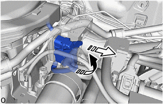
(a) Release the lock lever and disconnect the connector from the brake actuator assembly.
.png) |
Release the lock lever |
.png) |
Disconnect the connector |
NOTICE:
Be careful not to allow any brake fluid to enter the connector.
|
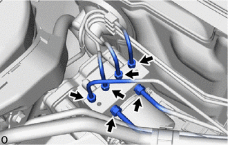
(b) Use tags or make a memo to identify the places to reconnect the brake tubes. |
|
.png)
|
(c) Using a 10 mm and 12 mm union nut wrench, disconnect the 6 brake tubes from the brake actuator assembly. |
|
|
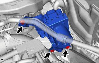
(d) Remove the bolt, 2 nuts and brake actuator with bracket from the vehicle. NOTICE:
HINT: Remove the brake actuator with bracket while avoiding the brake tubes. |
|
12. REMOVE BRAKE ACTUATOR ASSEMBLY
|
(a) Loosen the 2 nuts. |
|
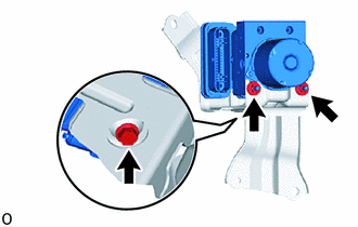
(b) Remove the bolt and brake actuator assembly from the brake actuator bracket assembly.
NOTICE:
- Do not hold the brake actuator assembly by the connector.
- Be careful not to allow any brake fluid to enter the connector.
- Do not drop the brake actuator assembly when carrying it.
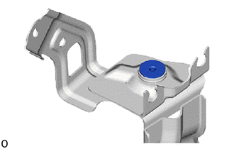
13. REMOVE NO. 1 BRAKE ACTUATOR CASE COLLAR
|
(a) Remove the No. 1 brake actuator case collar from the brake actuator bracket cushion. |
|
14. REMOVE BRAKE ACTUATOR BRACKET CUSHION
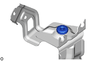
(a) Remove the brake actuator bracket cushion from the brake actuator bracket assembly.
 Installation
INSTALLATION
CAUTION / NOTICE / HINT
PROCEDURE
1. INSTALL BRAKE ACTUATOR BRACKET CUSHION
(a) Install the brake actuator bracket cushion to the brake actuator bracket
assembly.
2. INSTALL NO. 1 ...
 Brake Hold Switch
Components
COMPONENTS
ILLUSTRATION
*1
BRAKE HOLD SWITCH (ELECTRIC PARKING BRAKE SWITCH ASSEMBLY)
-
-
Inspection
INSPECTION
PROCEDURE
1 ...
Other materials:
Toyota CH-R Service Manual > Lighting System: Footwell Light Circuit
DESCRIPTION
The main body ECU (multiplex network body ECU) controls the door mirror foot
lights.
WIRING DIAGRAM
PROCEDURE
1.
PERFORM ACTIVE TEST USING TECHSTREAM
(a) Connect the Techstream to the DLC3.
(b) Turn the ignition switch to ON.
(c) Turn the Techst ...
Toyota CH-R Service Manual > Airbag System: Precaution
PRECAUTION
HINT:
In the airbag system, the parts listed below are collectively referred to as
the airbag sensors.
Airbag sensor assembly
Front airbag sensor
Door side airbag sensors
No. 1 side airbag sensor
Floor side airbag sensor
No. 2 side airbag sensor
...
Toyota C-HR (AX20) 2023-2026 Owner's Manual
Toyota CH-R Owners Manual
- For safety and security
- Instrument cluster
- Operation of each component
- Driving
- Interior features
- Maintenance and care
- When trouble arises
- Vehicle specifications
- For owners
Toyota CH-R Service Manual
- Introduction
- Maintenance
- Audio / Video
- Cellular Communication
- Navigation / Multi Info Display
- Park Assist / Monitoring
- Brake (front)
- Brake (rear)
- Brake Control / Dynamic Control Systems
- Brake System (other)
- Parking Brake
- Axle And Differential
- Drive Shaft / Propeller Shaft
- K114 Cvt
- 3zr-fae Battery / Charging
- Networking
- Power Distribution
- Power Assist Systems
- Steering Column
- Steering Gear / Linkage
- Alignment / Handling Diagnosis
- Front Suspension
- Rear Suspension
- Tire / Wheel
- Tire Pressure Monitoring
- Door / Hatch
- Exterior Panels / Trim
- Horn
- Lighting (ext)
- Mirror (ext)
- Window / Glass
- Wiper / Washer
- Door Lock
- Heating / Air Conditioning
- Interior Panels / Trim
- Lighting (int)
- Meter / Gauge / Display
- Mirror (int)
- Power Outlets (int)
- Pre-collision
- Seat
- Seat Belt
- Supplemental Restraint Systems
- Theft Deterrent / Keyless Entry

0.0413