Toyota CH-R Service Manual: Radio Receiver(for Radio And Display Type)
Components
COMPONENTS
ILLUSTRATION
|
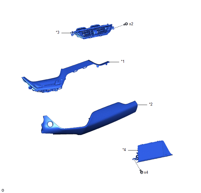
*1 |
INSTRUMENT CLUSTER FINISH LOWER CENTER PANEL SUB-ASSEMBLY |
*2 |
INSTRUMENT CLUSTER FINISH PANEL GARNISH ASSEMBLY |
|
*3 |
INSTRUMENT PANEL CENTER REGISTER ASSEMBLY |
*4 |
RADIO AND DISPLAY RECEIVER ASSEMBLY WITH BRACKET |
ILLUSTRATION
|
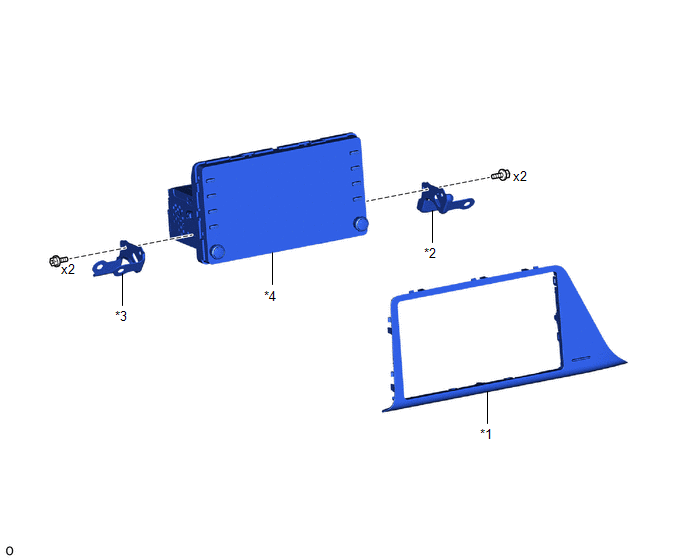
*1 |
INSTRUMENT CLUSTER FINISH CENTER PANEL SUB-ASSEMBLY |
*2 |
NO. 1 RADIO RECEIVER BRACKET |
|
*3 |
NO. 2 RADIO RECEIVER BRACKET |
*4 |
RADIO AND DISPLAY RECEIVER ASSEMBLY |
Removal
REMOVAL
PROCEDURE
1. REMOVE INSTRUMENT CLUSTER FINISH PANEL GARNISH ASSEMBLY
Click here
.gif)
2. REMOVE INSTRUMENT CLUSTER FINISH LOWER CENTER PANEL SUB-ASSEMBLY
Click here
3. REMOVE INSTRUMENT PANEL CENTER REGISTER ASSEMBLY
Click here
4. REMOVE RADIO AND DISPLAY RECEIVER ASSEMBLY WITH BRACKET
|
(a) Remove the 4 screws. |
|
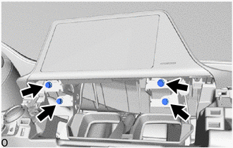
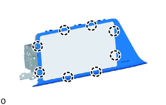
(b) Pull the radio and display receiver assembly with bracket toward the rear of the vehicle to disengage the claws and clips as shown in the illustration.
.png) |
Remove in this Direction |
(c) Disconnect each connector and remove the radio and display receiver assembly with bracket.
5. REMOVE INSTRUMENT CLUSTER FINISH CENTER PANEL SUB-ASSEMBLY
|
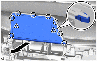
(a) Disengage the claws to remove the instrument cluster finish center panel sub assembly. |
|
6. REMOVE NO. 1 RADIO RECEIVER BRACKET
|
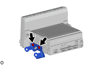
(a) Remove the 2 screws and No. 1 radio receiver bracket from the radio and display receiver assembly. |
|
7. REMOVE NO. 2 RADIO RECEIVER BRACKET
|
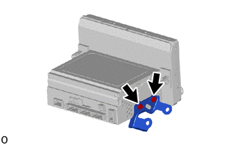
(a) Remove the 2 screws and No. 2 radio receiver bracket from the radio and display receiver assembly. |
|
Installation
INSTALLATION
PROCEDURE
1. INSTALL NO. 2 RADIO RECEIVER BRACKET
(a) Install the No. 2 radio receiver bracket with the 2 screws to the radio and display receiver assembly.
2. INSTALL NO. 1 RADIO RECEIVER BRACKET
(a) Install the No. 1 radio receiver bracket with the 2 screws to the radio and display receiver assembly.
3. INSTALL INSTRUMENT CLUSTER FINISH CENTER PANEL SUB-ASSEMBLY
|
(a) Engage the claws to install the instrument cluster finish center panel sub assembly. |
|
.png)
4. INSTALL RADIO AND DISPLAY RECEIVER ASSEMBLY WITH BRACKET
(a) Connect each connector.
(b) Engage the clips and claws to install the radio and display receiver assembly with bracket as shown in the illustration.
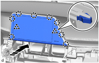
.png) |
Install in this Direction |
(c) Install the 4 screws.
5. INSTALL INSTRUMENT PANEL CENTER REGISTER ASSEMBLY
Click here
.gif)
6. INSTALL INSTRUMENT CLUSTER FINISH LOWER CENTER PANEL SUB-ASSEMBLY
Click here
7. INSTALL INSTRUMENT CLUSTER FINISH PANEL GARNISH ASSEMBLY
Click here
 Radio Receiver(for Radio Receiver Type)
Components
COMPONENTS
ILLUSTRATION
*1
INSTRUMENT CLUSTER FINISH CENTER PANEL SUB-ASSEMBLY
*2
RADIO RECEIVER ASSEMBLY WITH BRACKET
ILLUSTRAT ...

Other materials:
Toyota CH-R Service Manual > Front Seat Assembly: Removal
REMOVAL
CAUTION / NOTICE / HINT
The necessary procedures (adjustment, calibration, initialization, or registration)
that must be performed after parts are removed, installed, or replaced during the
front seat assembly removal/installation are shown below.
Necessary Procedure After Parts Remov ...
Toyota CH-R Service Manual > Blind Spot Monitor System: Parts Location
PARTS LOCATION
ILLUSTRATION
*1
OUTER REAR VIEW MIRROR ASSEMBLY LH
*2
OUTER REAR VIEW MIRROR ASSEMBLY RH
*3
BRAKE ACTUATOR ASSEMBLY
- SKID CONTROL ECU
*4
ECM
ILLUSTRATION
*1
...
Toyota CH-R Owners Manual
- For safety and security
- Instrument cluster
- Operation of each component
- Driving
- Interior features
- Maintenance and care
- When trouble arises
- Vehicle specifications
- For owners
Toyota CH-R Service Manual
- Introduction
- Maintenance
- Audio / Video
- Cellular Communication
- Navigation / Multi Info Display
- Park Assist / Monitoring
- Brake (front)
- Brake (rear)
- Brake Control / Dynamic Control Systems
- Brake System (other)
- Parking Brake
- Axle And Differential
- Drive Shaft / Propeller Shaft
- K114 Cvt
- 3zr-fae Battery / Charging
- Networking
- Power Distribution
- Power Assist Systems
- Steering Column
- Steering Gear / Linkage
- Alignment / Handling Diagnosis
- Front Suspension
- Rear Suspension
- Tire / Wheel
- Tire Pressure Monitoring
- Door / Hatch
- Exterior Panels / Trim
- Horn
- Lighting (ext)
- Mirror (ext)
- Window / Glass
- Wiper / Washer
- Door Lock
- Heating / Air Conditioning
- Interior Panels / Trim
- Lighting (int)
- Meter / Gauge / Display
- Mirror (int)
- Power Outlets (int)
- Pre-collision
- Seat
- Seat Belt
- Supplemental Restraint Systems
- Theft Deterrent / Keyless Entry

0.0096