Toyota CH-R Service Manual: Parts Location
PARTS LOCATION
ILLUSTRATION
|
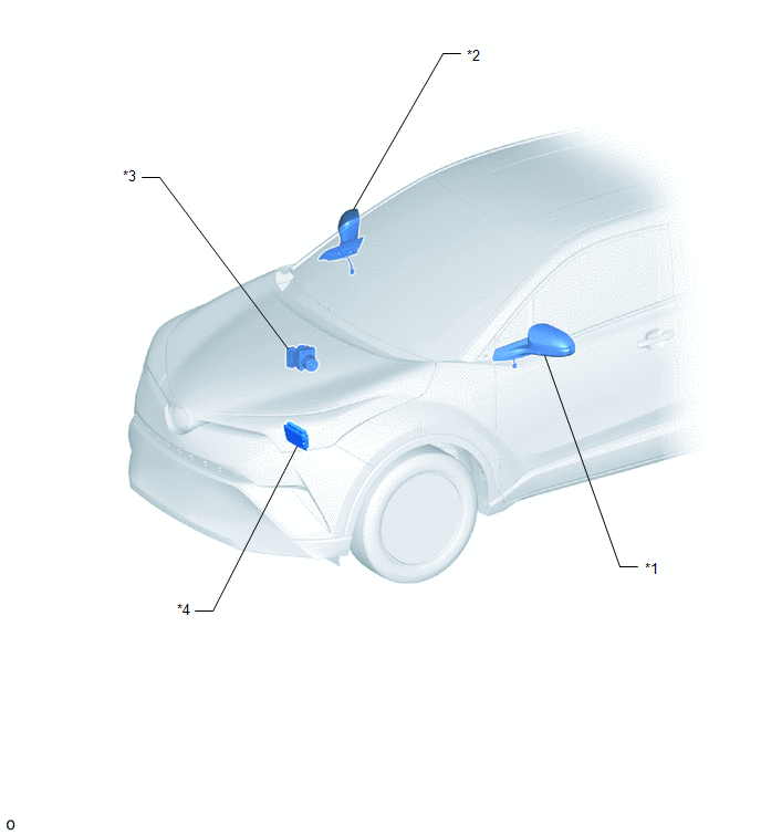
*1 |
OUTER REAR VIEW MIRROR ASSEMBLY LH |
*2 |
OUTER REAR VIEW MIRROR ASSEMBLY RH |
|
*3 |
BRAKE ACTUATOR ASSEMBLY - SKID CONTROL ECU |
*4 |
ECM |
ILLUSTRATION
|
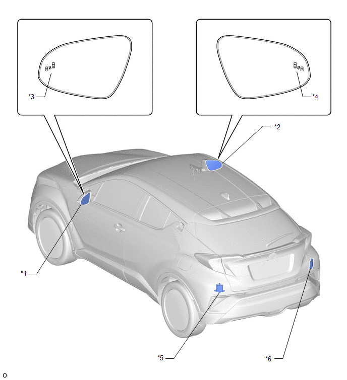
*1 |
OUTER MIRROR LH |
*2 |
OUTER MIRROR RH |
|
*3 |
OUTER REAR VIEW MIRROR INDICATOR LH |
*4 |
OUTER REAR VIEW MIRROR INDICATOR RH |
|
*5 |
BLIND SPOT MONITOR SENSOR LH (MASTER) |
*6 |
BLIND SPOT MONITOR SENSOR RH (SLAVE) |
ILLUSTRATION
|
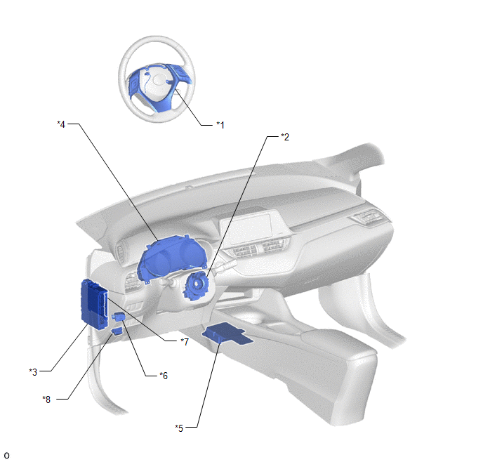
*1 |
STEERING PAD SWITCH ASSEMBLY |
*2 |
SPIRAL CABLE WITH SENSOR SUB-ASSEMBLY - STEERING SENSOR |
|
*3 |
INSTRUMENT PANEL JUNCTION BLOCK ASSEMBLY - ECU-IG1 NO. 4 FUSE |
*4 |
COMBINATION METER ASSEMBLY - MULTI-INFORMATION DISPLAY |
|
*5 |
AIRBAG SENSOR ASSEMBLY |
*6 |
RCTA BUZZER (BLIND SPOT MONITOR BUZZER) |
|
*7 |
MAIN BODY ECU (MULTIPLEX NETWORK BODY ECU) |
*8 |
DLC3 |
 Precaution
PRECAUTION
IGNITION SWITCH EXPRESSIONS
(a) The type of ignition switch used on this model differs depending on the specifications
of the vehicle. The expressions listed in the table below are used ...
 System Diagram
SYSTEM DIAGRAM
...
Other materials:
Toyota CH-R Service Manual > Airbag System: Trouble in Passenger Airbag ON/OFF Indicator
DESCRIPTION
This circuit detects the airbag cut off switch cylinder sub-assembly status.
The passenger airbag ON/OFF indicator comes on to inform the driver of the instrument
panel passenger without door airbag assembly status (activated or deactivated).
HINT:
Approximately 6 seconds after the ...
Toyota CH-R Service Manual > Pre-collision System: Stop Light Relay Circuit (C1A4B)
DESCRIPTION
The skid control ECU (brake actuator assembly) sends a stop light operation request
signal to the stop light switch assembly. If the skid control ECU (brake actuator
assembly) detects a malfunction in the stop light switch assembly circuit, the millimeter
wave radar sensor assembl ...
Toyota C-HR (AX20) 2023-2026 Owner's Manual
Toyota CH-R Owners Manual
- For safety and security
- Instrument cluster
- Operation of each component
- Driving
- Interior features
- Maintenance and care
- When trouble arises
- Vehicle specifications
- For owners
Toyota CH-R Service Manual
- Introduction
- Maintenance
- Audio / Video
- Cellular Communication
- Navigation / Multi Info Display
- Park Assist / Monitoring
- Brake (front)
- Brake (rear)
- Brake Control / Dynamic Control Systems
- Brake System (other)
- Parking Brake
- Axle And Differential
- Drive Shaft / Propeller Shaft
- K114 Cvt
- 3zr-fae Battery / Charging
- Networking
- Power Distribution
- Power Assist Systems
- Steering Column
- Steering Gear / Linkage
- Alignment / Handling Diagnosis
- Front Suspension
- Rear Suspension
- Tire / Wheel
- Tire Pressure Monitoring
- Door / Hatch
- Exterior Panels / Trim
- Horn
- Lighting (ext)
- Mirror (ext)
- Window / Glass
- Wiper / Washer
- Door Lock
- Heating / Air Conditioning
- Interior Panels / Trim
- Lighting (int)
- Meter / Gauge / Display
- Mirror (int)
- Power Outlets (int)
- Pre-collision
- Seat
- Seat Belt
- Supplemental Restraint Systems
- Theft Deterrent / Keyless Entry

0.0066