Toyota CH-R Service Manual: Parts Location
PARTS LOCATION
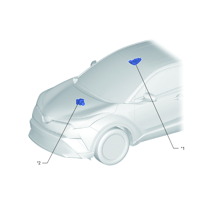
ILLUSTRATION
|
*1 |
MAP LIGHT ASSEMBLY (TELEPHONE MICROPHONE ASSEMBLY) |
*2 |
SKID CONTROL ECU (BRAKE ACTUATOR ASSEMBLY) |
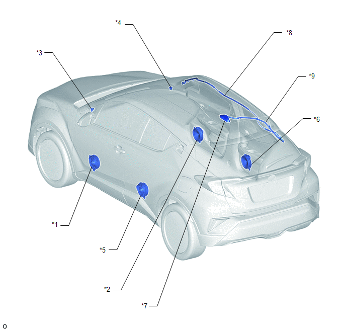
ILLUSTRATION
|
*1 |
FRONT NO. 1 SPEAKER ASSEMBLY LH |
*2 |
FRONT NO. 1 SPEAKER ASSEMBLY RH |
|
*3 |
FRONT NO. 2 SPEAKER ASSEMBLY LH |
*4 |
FRONT NO. 2 SPEAKER ASSEMBLY RH |
|
*5 |
REAR SPEAKER ASSEMBLY LH |
*6 |
REAR SPEAKER ASSEMBLY RH |
|
*7 |
ROOF ANTENNA ASSEMBLY - AM - FM - SiriusXM (w/ SXM Function) |
*8 |
NO. 2 ANTENNA CORD SUB-ASSEMBLY |
|
*9 |
NO. 3 ANTENNA CORD SUB-ASSEMBLY |
- |
- |
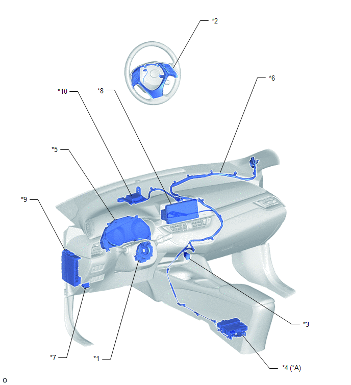
ILLUSTRATION
|
*A |
w/ Manual (SOS) Switch |
- |
- |
|
*1 |
SPIRAL CABLE WITH SENSOR SUB-ASSEMBLY |
*2 |
STEERING PAD SWITCH ASSEMBLY |
|
*3 |
NO. 1 STEREO JACK ADAPTER ASSEMBLY |
*4 |
DCM (TELEMATICS TRANSCEIVER) |
|
*5 |
COMBINATION METER ASSEMBLY |
*6 |
ANTENNA CORD SUB-ASSEMBLY |
|
*7 |
DLC3 |
*8 |
RADIO AND DISPLAY RECEIVER ASSEMBLY |
|
*9 |
INSTRUMENT PANEL JUNCTION BLOCK ASSEMBLY - RADIO FUSE - PANEL FUSE - ECU-ACC FUSE - ECU-IG1 NO. 4 FUSE |
*10 |
NAVIGATION ANTENNA ASSEMBLY - GPS - TEL Sub |
 Precaution
PRECAUTION
IGNITION SWITCH EXPRESSIONS
(a) The type of ignition switch used on this model differs depending on the specifications
of the vehicle. The expressions listed in the table below are used ...
 System Diagram
SYSTEM DIAGRAM
...
Other materials:
Toyota CH-R Service Manual > Steering Gear: Inspection
INSPECTION
PROCEDURE
1. INSPECT TIE ROD END SUB-ASSEMBLY LH
(a) Secure the tie rod end sub-assembly LH in a vise between aluminum
plates.
NOTICE:
Do not overtighten the vise.
(b) Install the nut to the stud bolt.
(c) Flip the ...
Toyota CH-R Service Manual > Personal Light: Inspection
INSPECTION
PROCEDURE
1. INSPECT MAP LIGHT ASSEMBLY
(a) Check the map light.
(1) Apply battery voltage to the map light assembly and check that the
map light comes on.
OK:
Battery Connection
Switch Condition
Specified Cond ...
Toyota C-HR (AX20) 2023-2026 Owner's Manual
Toyota CH-R Owners Manual
- For safety and security
- Instrument cluster
- Operation of each component
- Driving
- Interior features
- Maintenance and care
- When trouble arises
- Vehicle specifications
- For owners
Toyota CH-R Service Manual
- Introduction
- Maintenance
- Audio / Video
- Cellular Communication
- Navigation / Multi Info Display
- Park Assist / Monitoring
- Brake (front)
- Brake (rear)
- Brake Control / Dynamic Control Systems
- Brake System (other)
- Parking Brake
- Axle And Differential
- Drive Shaft / Propeller Shaft
- K114 Cvt
- 3zr-fae Battery / Charging
- Networking
- Power Distribution
- Power Assist Systems
- Steering Column
- Steering Gear / Linkage
- Alignment / Handling Diagnosis
- Front Suspension
- Rear Suspension
- Tire / Wheel
- Tire Pressure Monitoring
- Door / Hatch
- Exterior Panels / Trim
- Horn
- Lighting (ext)
- Mirror (ext)
- Window / Glass
- Wiper / Washer
- Door Lock
- Heating / Air Conditioning
- Interior Panels / Trim
- Lighting (int)
- Meter / Gauge / Display
- Mirror (int)
- Power Outlets (int)
- Pre-collision
- Seat
- Seat Belt
- Supplemental Restraint Systems
- Theft Deterrent / Keyless Entry

0.0103