Toyota CH-R Service Manual: Installation
INSTALLATION
CAUTION / NOTICE / HINT
HINT:
- Use the same procedure for the RH side and LH side.
- The following procedure is for the LH side.
- The front speed sensor rotor is a component of the front axle hub sub-assembly. If the front speed sensor rotor is malfunctioning, replace the front axle hub sub-assembly.
PROCEDURE
1. INSTALL FRONT SPEED SENSOR
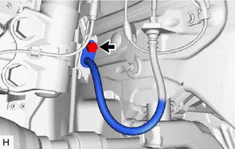
(a) Install the front speed sensor to the steering knuckle with the bolt.
Torque:
8.5 N·m {87 kgf·cm, 75 in·lbf}
NOTICE:
- Keep the tip of the front speed sensor and installation hole free of foreign matter.
- Firmly insert the front speed sensor body into the steering knuckle before tightening the bolt.
- After installing the front speed sensor to the steering knuckle, make sure that there is no clearance between the front speed sensor stay and steering knuckle. Also make sure that no foreign matter is stuck between the parts.
|
(b) Engage the clamp to the front shock absorber assembly. NOTICE: Do not twist the front speed sensor wire harness when installing it. |
|
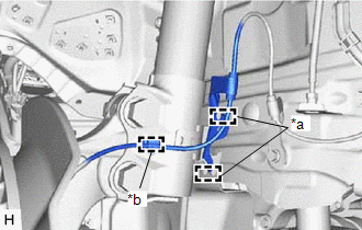
(c) Engage the 2 hooks of front speed sensor clamp to the front shock absorber assembly.
NOTICE:
Do not twist the front speed sensor wire harness when installing it.
|
(d) Install the front flexible hose to the front shock absorber assembly with the bolt. Torque: 29 N·m {296 kgf·cm, 21 ft·lbf} |
|
(e) Install the 2 front speed sensor clamps with the 2 bolts.
Torque:
8.5 N·m {87 kgf·cm, 75 in·lbf}
NOTICE:
Do not twist the front speed sensor wire harness when installing it.
(f) Engage the clamp to the vehicle body.
NOTICE:
Do not twist the front speed sensor wire harness when installing it.
(g) Engage the clamp to the vehicle body.
NOTICE:
Do not twist the front speed sensor wire harness when installing it.
(h) Connect the connector.
(i) Return the front fender liner to its original position.
2. INSTALL FRONT FENDER LINER
(a) Install the front fender liner with the 3 clips.
(b) Install the 4 screws.
3. INSTALL ROCKER PANEL MOULDING
Click here
.gif)
4. INSTALL FRONT WHEEL
Click here
5. CHECK FOR SPEED SENSOR SIGNAL
Click here
 Removal
REMOVAL
CAUTION / NOTICE / HINT
HINT:
Use the same procedure for the RH side and LH side.
The following procedure is for the LH side.
The front speed sensor rotor is a component of ...
 Rear Speed Sensor
Components
COMPONENTS
ILLUSTRATION
*1
REAR AXLE HUB AND BEARING ASSEMBLY
*2
REAR DISC
*3
REAR DISC BRAKE CALIPER ASSEMBLY ...
Other materials:
Toyota CH-R Service Manual > Door Control Transmitter(w/o Smart Key System): Installation
INSTALLATION
CAUTION / NOTICE / HINT
NOTICE:
Take extra care when handling these precision electronic components.
PROCEDURE
1. INSTALL TRANSMITTER BATTERY
(a) Install a new transmitter battery with the positive (+) side facing upward,
as shown in the illustration.
Inst ...
Toyota CH-R Service Manual > Front Stabilizer Bar: Removal
REMOVAL
CAUTION / NOTICE / HINT
The necessary procedures (adjustment, calibration, initialization, or registration)
that must be performed after parts are removed and installed, or replaced during
front stabilizer bar removal/installation are shown below.
Necessary Procedures After Parts Remo ...
Toyota C-HR (AX20) 2023-2026 Owner's Manual
Toyota CH-R Owners Manual
- For safety and security
- Instrument cluster
- Operation of each component
- Driving
- Interior features
- Maintenance and care
- When trouble arises
- Vehicle specifications
- For owners
Toyota CH-R Service Manual
- Introduction
- Maintenance
- Audio / Video
- Cellular Communication
- Navigation / Multi Info Display
- Park Assist / Monitoring
- Brake (front)
- Brake (rear)
- Brake Control / Dynamic Control Systems
- Brake System (other)
- Parking Brake
- Axle And Differential
- Drive Shaft / Propeller Shaft
- K114 Cvt
- 3zr-fae Battery / Charging
- Networking
- Power Distribution
- Power Assist Systems
- Steering Column
- Steering Gear / Linkage
- Alignment / Handling Diagnosis
- Front Suspension
- Rear Suspension
- Tire / Wheel
- Tire Pressure Monitoring
- Door / Hatch
- Exterior Panels / Trim
- Horn
- Lighting (ext)
- Mirror (ext)
- Window / Glass
- Wiper / Washer
- Door Lock
- Heating / Air Conditioning
- Interior Panels / Trim
- Lighting (int)
- Meter / Gauge / Display
- Mirror (int)
- Power Outlets (int)
- Pre-collision
- Seat
- Seat Belt
- Supplemental Restraint Systems
- Theft Deterrent / Keyless Entry

0.0076