Toyota CH-R Service Manual: Removal
REMOVAL
CAUTION / NOTICE / HINT
HINT:
- Use the same procedure for the RH side and LH side.
- The following procedure is for the LH side.
- The front speed sensor rotor is a component of the front axle hub sub-assembly. If the front speed sensor rotor is malfunctioning, replace the front axle hub sub-assembly.
PROCEDURE
1. REMOVE FRONT WHEEL
Click here
.gif)
2. REMOVE ROCKER PANEL MOULDING
Click here
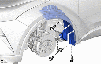
3. SEPARATE FRONT FENDER LINER
|
(a) Remove the 4 screws. |
|
|
(b) Remove the 3 clips and separate the front fender liner. |
|
4. REMOVE FRONT SPEED SENSOR
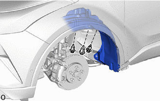
(a) Turn back the front fender liner.
|
(b) Disconnect the connector. |
|
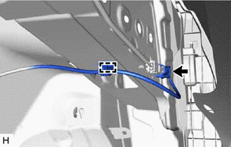
(c) Disengage the clamp from the vehicle body.
|
(d) Disengage the clamp from the vehicle body. |
|
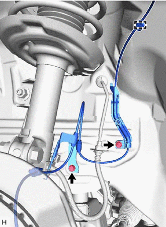
(e) Remove the 2 bolts and separate the 2 front speed sensor clamps.
|
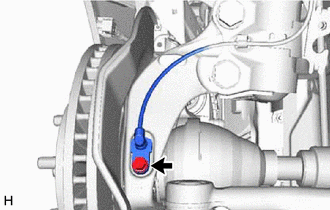
(f) Remove the bolt and separate the front flexible hose and front speed sensor clamp from the front shock absorber assembly. |
|
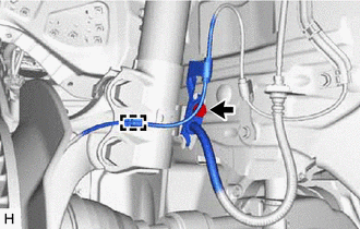
(g) Disengage the clamp from the front shock absorber assembly.
|
(h) Remove the bolt and front speed sensor from the steering knuckle. NOTICE:
|
|
 Components
COMPONENTS
ILLUSTRATION
*1
FRONT FENDER LINER
*2
FRONT SPEED SENSOR
*3
FRONT FLEXIBLE HOSE
-
-
...
 Installation
INSTALLATION
CAUTION / NOTICE / HINT
HINT:
Use the same procedure for the RH side and LH side.
The following procedure is for the LH side.
The front speed sensor rotor is a componen ...
Other materials:
Toyota CH-R Service Manual > Brake Booster: Disassembly
DISASSEMBLY
PROCEDURE
1. REMOVE BRAKE VACUUM CHECK VALVE ASSEMBLY
(a) Remove the brake vacuum check valve assembly from the brake booster assembly.
(b) Remove the check valve grommet from the brake booster assembly.
2. REMOVE VACUUM WARNING SWITCH ASSEMBLY
(a) Remove the vacuum warning switc ...
Toyota CH-R Service Manual > Theft Deterrent System: Operation History List
OPERATION HISTORY LIST
NOTICE:
If the vehicle or vehicle controls are operated (for example, during
initial inspection when the vehicle is brought in for repair) before operation
history has been read out and saved, the operation history information could
be lost.
The funct ...
Toyota C-HR (AX20) 2023-2026 Owner's Manual
Toyota CH-R Owners Manual
- For safety and security
- Instrument cluster
- Operation of each component
- Driving
- Interior features
- Maintenance and care
- When trouble arises
- Vehicle specifications
- For owners
Toyota CH-R Service Manual
- Introduction
- Maintenance
- Audio / Video
- Cellular Communication
- Navigation / Multi Info Display
- Park Assist / Monitoring
- Brake (front)
- Brake (rear)
- Brake Control / Dynamic Control Systems
- Brake System (other)
- Parking Brake
- Axle And Differential
- Drive Shaft / Propeller Shaft
- K114 Cvt
- 3zr-fae Battery / Charging
- Networking
- Power Distribution
- Power Assist Systems
- Steering Column
- Steering Gear / Linkage
- Alignment / Handling Diagnosis
- Front Suspension
- Rear Suspension
- Tire / Wheel
- Tire Pressure Monitoring
- Door / Hatch
- Exterior Panels / Trim
- Horn
- Lighting (ext)
- Mirror (ext)
- Window / Glass
- Wiper / Washer
- Door Lock
- Heating / Air Conditioning
- Interior Panels / Trim
- Lighting (int)
- Meter / Gauge / Display
- Mirror (int)
- Power Outlets (int)
- Pre-collision
- Seat
- Seat Belt
- Supplemental Restraint Systems
- Theft Deterrent / Keyless Entry

0.0111