Toyota CH-R Service Manual: Disassembly
DISASSEMBLY
PROCEDURE
1. REMOVE BRAKE VACUUM CHECK VALVE ASSEMBLY
(a) Remove the brake vacuum check valve assembly from the brake booster assembly.
(b) Remove the check valve grommet from the brake booster assembly.
2. REMOVE VACUUM WARNING SWITCH ASSEMBLY
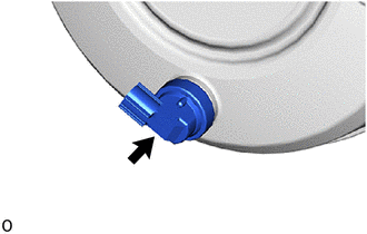
(a) Remove the vacuum warning switch assembly from the brake booster assembly.
(b) Remove the check valve grommet from the brake booster assembly.
 Removal
REMOVAL
CAUTION / NOTICE / HINT
The necessary procedures (adjustment, calibration, initialization, or registration)
that must be performed after parts are removed, installed, or replaced during th ...
 Inspection
INSPECTION
PROCEDURE
1. INSPECT BRAKE VACUUM CHECK VALVE ASSEMBLY
(a) Check that there is ventilation from the booster to the engine, and
no ventilation from the engine to the booste ...
Other materials:
Toyota CH-R Service Manual > Front Brake: Components
COMPONENTS
ILLUSTRATION
*1
FRONT DISC BRAKE ANTI-SQUEAL SHIM KIT
*2
FRONT DISC BRAKE CYLINDER ASSEMBLY
*3
FRONT DISC BRAKE PAD
*4
FRONT FLEXIBLE HOSE
*5
FRONT DISC BRAKE ANTI ...
Toyota CH-R Service Manual > Key Reminder Warning System: Terminals Of Ecu
TERMINALS OF ECU
CHECK MAIN BODY ECU (MULTIPLEX NETWORK BODY ECU) AND INSTRUMENT PANEL JUNCTION
BLOCK ASSEMBLY
*A
Main Body ECU (Multiplex Network Body ECU) with 2 Connectors
-
-
*1
Main Body ECU (Multiplex Network Body EC ...
Toyota C-HR (AX20) 2023-2026 Owner's Manual
Toyota CH-R Owners Manual
- For safety and security
- Instrument cluster
- Operation of each component
- Driving
- Interior features
- Maintenance and care
- When trouble arises
- Vehicle specifications
- For owners
Toyota CH-R Service Manual
- Introduction
- Maintenance
- Audio / Video
- Cellular Communication
- Navigation / Multi Info Display
- Park Assist / Monitoring
- Brake (front)
- Brake (rear)
- Brake Control / Dynamic Control Systems
- Brake System (other)
- Parking Brake
- Axle And Differential
- Drive Shaft / Propeller Shaft
- K114 Cvt
- 3zr-fae Battery / Charging
- Networking
- Power Distribution
- Power Assist Systems
- Steering Column
- Steering Gear / Linkage
- Alignment / Handling Diagnosis
- Front Suspension
- Rear Suspension
- Tire / Wheel
- Tire Pressure Monitoring
- Door / Hatch
- Exterior Panels / Trim
- Horn
- Lighting (ext)
- Mirror (ext)
- Window / Glass
- Wiper / Washer
- Door Lock
- Heating / Air Conditioning
- Interior Panels / Trim
- Lighting (int)
- Meter / Gauge / Display
- Mirror (int)
- Power Outlets (int)
- Pre-collision
- Seat
- Seat Belt
- Supplemental Restraint Systems
- Theft Deterrent / Keyless Entry

0.0093