Toyota CH-R Service Manual: Removal
REMOVAL
CAUTION / NOTICE / HINT
The necessary procedures (adjustment, calibration, initialization, or registration) that must be performed after parts are removed, installed, or replaced during the brake booster assembly removal/installation are shown below.
Necessary Procedure After Parts Removed/Installed/Replaced|
Replacement Part or Procedure |
Necessary Procedures |
Effects / Inoperative when not performed |
Link |
|---|---|---|---|
|
Disconnect cable from negative battery terminal |
Memorize steering angle neutral point |
Lane departure alert system (w/ Steering Control) |
|
|
Pre-collision system |
|||
|
Initialize back door lock |
Power door lock control system |
|
NOTICE:
Make sure to release vacuum from the brake booster assembly before removing the master cylinder sub-assembly from the brake booster assembly.
PROCEDURE
1. REMOVE NO. 1 AIR DUCT
Click here
.gif)
2. REMOVE BRAKE MASTER CYLINDER SUB-ASSEMBLY
Click here
3. REMOVE BRAKE PEDAL RETURN SPRING
Click here
4. LOOSEN CLEVIS LOCK NUT
|
(a) Loosen the clevis lock nut of the brake master cylinder push rod clevis. |
|
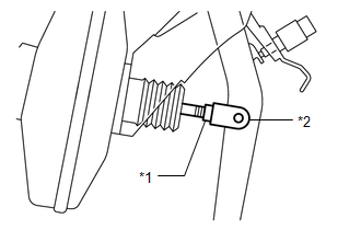
5. REMOVE PUSH ROD PIN
Click here
6. REMOVE NO. 1 ENGINE UNDER COVER
Click here
7. REMOVE DASH PANEL HEAT INSULATOR
|
(a) Remove the nut. |
|
|
(b) Remove the 2 nuts and the dash panel heat insulator. |
|
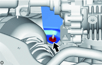
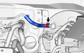
8. DISCONNECT CHECK VALVE TO CONNECTOR TUBE HOSE
|
(a) Slide the clip and disconnect the check valve to connector tube hose from the brake booster assembly. |
|
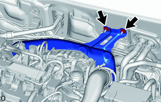
9. REMOVE BRAKE BOOSTER ASSEMBLY
|
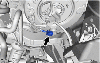
(a) Disconnect the vacuum warning switch connector. |
|
|
(b) Disengage the 5 camps to remove the No. 1 brake tube clamp from the brake tubes. |
|
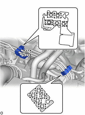
(c) Disengage the 5 clamps to separate the No. 2 brake tube clamps from the brake tubes.
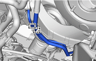
(d) Disengage the clamp to remove the No. 2 brake tube clamp from the vehicle body.
|
(e) Disengage the 2 clamps to separate the fuel pipe from the fuel pipe clamp. |
|
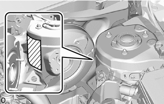
(f) Apply protective tape around the vehicle body.
.png) |
Protective Tape |
|
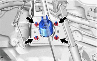
(g) Remove the 4 nuts and push the brake booster assembly toward the engine compartment. NOTICE: Do not apply excessive force to the brake lines. |
|
(h) Remove the brake master cylinder push rod clevis and lock nut from the brake booster assembly.
(i) Remove the brake booster assembly from the vehicle body.
NOTICE:
Do not apply excessive force to the brake lines or refrigerant lines.
10. REMOVE BRAKE BOOSTER GASKET
(a) Remove the brake booster gasket from the brake booster assembly.
 On-vehicle Inspection
ON-VEHICLE INSPECTION
PROCEDURE
1. INSPECT BRAKE BOOSTER ASSEMBLY
(a) Airtightness check
(1) Start the engine and stop it after 1 or 2 minutes. Slowly depress
the brake pedal severa ...
 Disassembly
DISASSEMBLY
PROCEDURE
1. REMOVE BRAKE VACUUM CHECK VALVE ASSEMBLY
(a) Remove the brake vacuum check valve assembly from the brake booster assembly.
(b) Remove the check valve grommet from the brak ...
Other materials:
Toyota CH-R Service Manual > Instrument Panel Safety Pad: Removal
REMOVAL
CAUTION / NOTICE / HINT
The necessary procedures (adjustment, calibration, initialization, or registration)
that must be performed after parts are removed, installed, or replaced during the
instrument panel safety pad sub-assembly removal/installation are shown below.
Necessary Proced ...
Toyota CH-R Service Manual > Park Assist / Monitoring: Blind Spot Monitor Sensor
Components
COMPONENTS
ILLUSTRATION
*1
BLIND SPOT MONITOR BRACKET LH
*2
BLIND SPOT MONITOR BRACKET RH
*3
BLIND SPOT MONITOR SENSOR LH
*4
BLIND SPOT MONITOR SENSOR RH
N*m (kgf ...
Toyota C-HR (AX20) 2023-2026 Owner's Manual
Toyota CH-R Owners Manual
- For safety and security
- Instrument cluster
- Operation of each component
- Driving
- Interior features
- Maintenance and care
- When trouble arises
- Vehicle specifications
- For owners
Toyota CH-R Service Manual
- Introduction
- Maintenance
- Audio / Video
- Cellular Communication
- Navigation / Multi Info Display
- Park Assist / Monitoring
- Brake (front)
- Brake (rear)
- Brake Control / Dynamic Control Systems
- Brake System (other)
- Parking Brake
- Axle And Differential
- Drive Shaft / Propeller Shaft
- K114 Cvt
- 3zr-fae Battery / Charging
- Networking
- Power Distribution
- Power Assist Systems
- Steering Column
- Steering Gear / Linkage
- Alignment / Handling Diagnosis
- Front Suspension
- Rear Suspension
- Tire / Wheel
- Tire Pressure Monitoring
- Door / Hatch
- Exterior Panels / Trim
- Horn
- Lighting (ext)
- Mirror (ext)
- Window / Glass
- Wiper / Washer
- Door Lock
- Heating / Air Conditioning
- Interior Panels / Trim
- Lighting (int)
- Meter / Gauge / Display
- Mirror (int)
- Power Outlets (int)
- Pre-collision
- Seat
- Seat Belt
- Supplemental Restraint Systems
- Theft Deterrent / Keyless Entry

0.0085