Toyota CH-R Service Manual: Rear Speed Sensor
Components
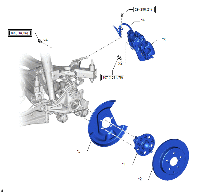
COMPONENTS
ILLUSTRATION
|
*1 |
REAR AXLE HUB AND BEARING ASSEMBLY |
*2 |
REAR DISC |
|
*3 |
REAR DISC BRAKE CALIPER ASSEMBLY |
*4 |
REAR FLEXIBLE HOSE |
|
*5 |
REAR DISC BRAKE DUST COVER SUB-ASSEMBLY |
- |
- |
.png) |
Tightening torque for "Major areas involving basic vehicle performance such as moving/turning/stopping" : N*m (kgf*cm, ft.*lbf) |
- |
- |
Removal
REMOVAL
PROCEDURE
1. REMOVE REAR AXLE HUB AND BEARING ASSEMBLY
HINT:
The rear speed sensor and sensor rotor are built into the rear axle hub sub-assembly. If the rear speed sensor or sensor rotor malfunctions, replace the rear axle hub sub-assembly.
Click here
.gif)
Installation
INSTALLATION
PROCEDURE
1. INSTALL REAR AXLE HUB AND BEARING ASSEMBLY
HINT:
The rear speed sensor and sensor rotor are built into the rear axle hub sub-assembly. If the rear speed sensor or sensor rotor malfunctions, replace the rear axle hub sub-assembly.
Click here
.gif)
 Installation
INSTALLATION
CAUTION / NOTICE / HINT
HINT:
Use the same procedure for the RH side and LH side.
The following procedure is for the LH side.
The front speed sensor rotor is a componen ...
 Steering Angle Sensor
Components
COMPONENTS
ILLUSTRATION
*1
SPIRAL CABLE SUB-ASSEMBLY
*2
STEERING SENSOR
Removal
REMOVAL
CAUTION / NOTICE / HINT
The necessa ...
Other materials:
Toyota CH-R Service Manual > Navigation System: Noise Occurs
PROCEDURE
1.
CHECK NOISE CONDITION
(a) Check from which direction the noise comes (front left or right, or rear
left or right).
OK:
The location of the noise source can be determined.
NG
GO TO STEP 3
OK
...
Toyota CH-R Service Manual > Audio / Video: Radio Receiver(for Radio Receiver Type)
Components
COMPONENTS
ILLUSTRATION
*1
INSTRUMENT CLUSTER FINISH CENTER PANEL SUB-ASSEMBLY
*2
RADIO RECEIVER ASSEMBLY WITH BRACKET
ILLUSTRATION
*1
NO. 1 RADIO BRACKET
*2
NO. 2 RADIO BRACKET
...
Toyota C-HR (AX20) 2023-2026 Owner's Manual
Toyota CH-R Owners Manual
- For safety and security
- Instrument cluster
- Operation of each component
- Driving
- Interior features
- Maintenance and care
- When trouble arises
- Vehicle specifications
- For owners
Toyota CH-R Service Manual
- Introduction
- Maintenance
- Audio / Video
- Cellular Communication
- Navigation / Multi Info Display
- Park Assist / Monitoring
- Brake (front)
- Brake (rear)
- Brake Control / Dynamic Control Systems
- Brake System (other)
- Parking Brake
- Axle And Differential
- Drive Shaft / Propeller Shaft
- K114 Cvt
- 3zr-fae Battery / Charging
- Networking
- Power Distribution
- Power Assist Systems
- Steering Column
- Steering Gear / Linkage
- Alignment / Handling Diagnosis
- Front Suspension
- Rear Suspension
- Tire / Wheel
- Tire Pressure Monitoring
- Door / Hatch
- Exterior Panels / Trim
- Horn
- Lighting (ext)
- Mirror (ext)
- Window / Glass
- Wiper / Washer
- Door Lock
- Heating / Air Conditioning
- Interior Panels / Trim
- Lighting (int)
- Meter / Gauge / Display
- Mirror (int)
- Power Outlets (int)
- Pre-collision
- Seat
- Seat Belt
- Supplemental Restraint Systems
- Theft Deterrent / Keyless Entry

0.0162