Toyota CH-R Service Manual: Steering Angle Sensor
Components
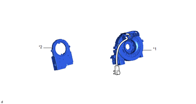
COMPONENTS
ILLUSTRATION
|
*1 |
SPIRAL CABLE SUB-ASSEMBLY |
*2 |
STEERING SENSOR |
Removal
REMOVAL
CAUTION / NOTICE / HINT
The necessary procedures (adjustment, calibration, initialization, or registration) that must be performed after parts are removed, installed, or replaced during the spiral cable with sensor sub-assembly removal/installation are shown below.
Necessary Procedure After Parts Removed/Installed/Replaced|
Replacement Part or Procedure |
Necessary Procedures |
Effects / Inoperative when not performed |
Link |
|---|---|---|---|
|
Disconnect cable from negative battery terminal |
Memorize steering angle neutral point |
Lane departure alert system (w/ Steering Control) |
|
|
Pre-collision system |
|||
|
Initialize back door lock |
Power door lock control system |
|
HINT:
- Use the same procedure for RHD and LHD vehicles.
- The following procedure is for LHD vehicles.
PROCEDURE
1. REMOVE SPIRAL CABLE WITH SENSOR SUB-ASSEMBLY
Click here
.gif)
2. REMOVE STEERING SENSOR
|
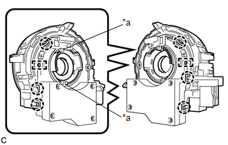
(a) Disengage the claws and pins, and remove the spiral cable sub-assembly from the steering sensor. NOTICE: Do not damage the pins of the spiral cable sub-assembly or guides of the steering sensor. |
|
Installation
INSTALLATION
CAUTION / NOTICE / HINT
HINT:
- Use the same procedure for RHD and LHD vehicles.
- The following procedure is for LHD vehicles.
PROCEDURE
1. INSTALL STEERING SENSOR
|
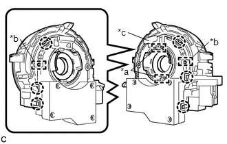
(a) Align the pins and guides, and engage the claws to install the steering sensor to the spiral cable sub-assembly. NOTICE:
|
|
|
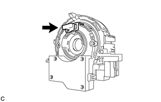
(b) Remove the lock pin from the steering sensor. |
|
2. INSTALL SPIRAL CABLE WITH SENSOR SUB-ASSEMBLY
Click here
.gif)
 Rear Speed Sensor
Components
COMPONENTS
ILLUSTRATION
*1
REAR AXLE HUB AND BEARING ASSEMBLY
*2
REAR DISC
*3
REAR DISC BRAKE CALIPER ASSEMBLY ...

Other materials:
Toyota CH-R Service Manual > Front Axle Hub: Installation
INSTALLATION
CAUTION / NOTICE / HINT
HINT:
Use the same procedure for the RH side and LH side.
The following procedure is for the LH side.
PROCEDURE
1. INSTALL FRONT AXLE HUB SUB-ASSEMBLY
(a) Secure the steering knuckle between aluminum plates in a vise.
NOTICE:
Do not over ...
Toyota CH-R Service Manual > Hood Lock Control Cable Assembly: Removal
REMOVAL
PROCEDURE
1. REMOVE FRONT WHEEL
Click here
2. REMOVE FRONT BUMPER ASSEMBLY
Click here
3. REMOVE FRONT FENDER MOULDING SUB-ASSEMBLY
Click here
4. REMOVE ROCKER PANEL MOULDING LH
Click here
5. REMOVE FRONT FENDER LINER LH
(a) Remove the 2 screws, 7 clips and front fe ...
Toyota C-HR (AX20) 2023-2026 Owner's Manual
Toyota CH-R Owners Manual
- For safety and security
- Instrument cluster
- Operation of each component
- Driving
- Interior features
- Maintenance and care
- When trouble arises
- Vehicle specifications
- For owners
Toyota CH-R Service Manual
- Introduction
- Maintenance
- Audio / Video
- Cellular Communication
- Navigation / Multi Info Display
- Park Assist / Monitoring
- Brake (front)
- Brake (rear)
- Brake Control / Dynamic Control Systems
- Brake System (other)
- Parking Brake
- Axle And Differential
- Drive Shaft / Propeller Shaft
- K114 Cvt
- 3zr-fae Battery / Charging
- Networking
- Power Distribution
- Power Assist Systems
- Steering Column
- Steering Gear / Linkage
- Alignment / Handling Diagnosis
- Front Suspension
- Rear Suspension
- Tire / Wheel
- Tire Pressure Monitoring
- Door / Hatch
- Exterior Panels / Trim
- Horn
- Lighting (ext)
- Mirror (ext)
- Window / Glass
- Wiper / Washer
- Door Lock
- Heating / Air Conditioning
- Interior Panels / Trim
- Lighting (int)
- Meter / Gauge / Display
- Mirror (int)
- Power Outlets (int)
- Pre-collision
- Seat
- Seat Belt
- Supplemental Restraint Systems
- Theft Deterrent / Keyless Entry

0.007