Toyota CH-R Service Manual: System Diagram
SYSTEM DIAGRAM
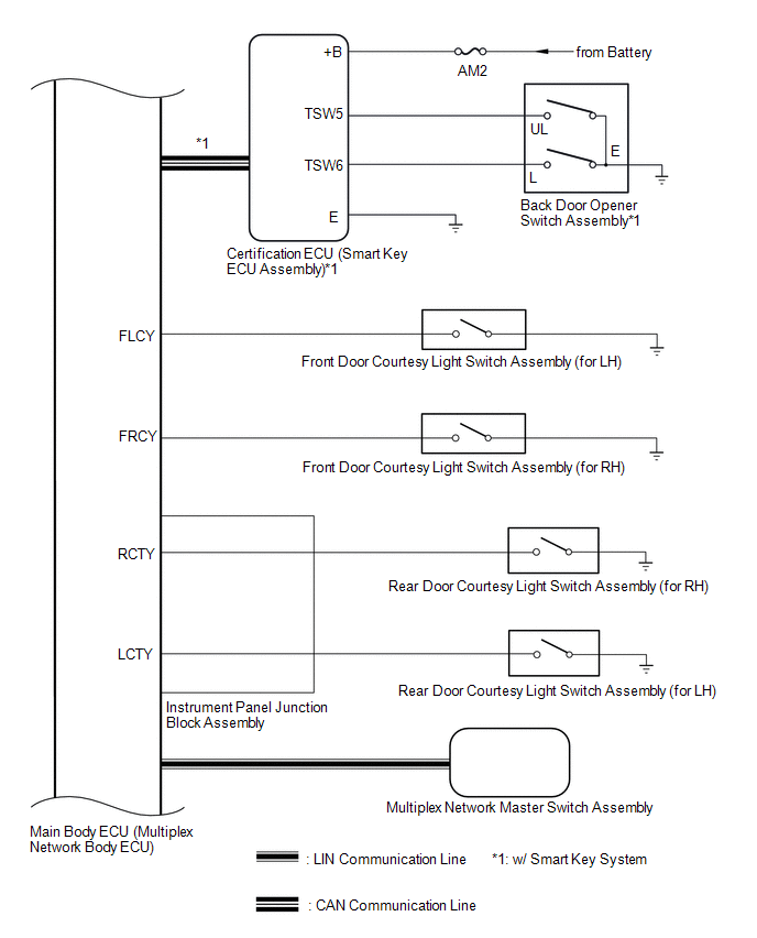
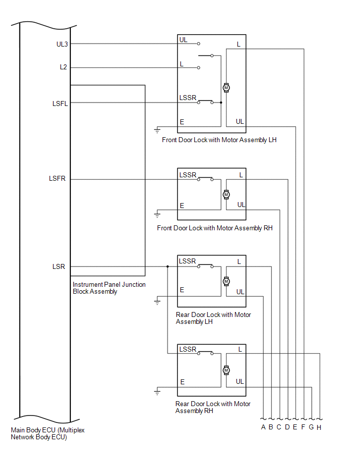
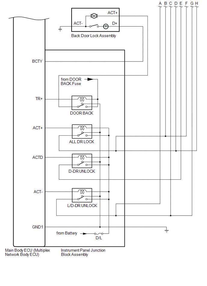
Power Door Lock Control System
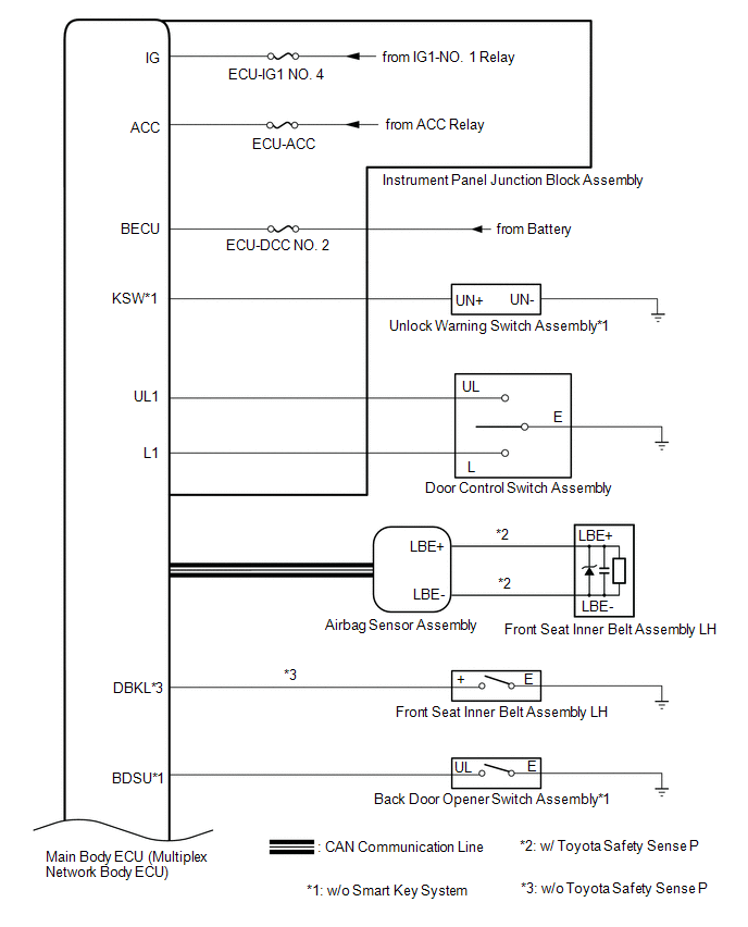
 Communication Table
|
Sender |
Receiver |
Signal |
Line |
|---|---|---|---|
|
Multiplex Network Master Switch Assembly |
Main Body ECU (Multiplex Network Body ECU) |
Door control switch signal |
LIN |
|
Certification ECU (Smart Key ECU Assembly)*1 |
Main Body ECU (Multiplex Network Body ECU) |
Back door opener switch signal |
CAN |
|
Airbag ECU assembly*2 |
Main Body ECU (Multiplex Network Body ECU) |
Front seat inner belt assembly LH buckle switch |
CAN |
- *1: w/ Smart Key System
- *2: w/ Toyota Safety Sense P
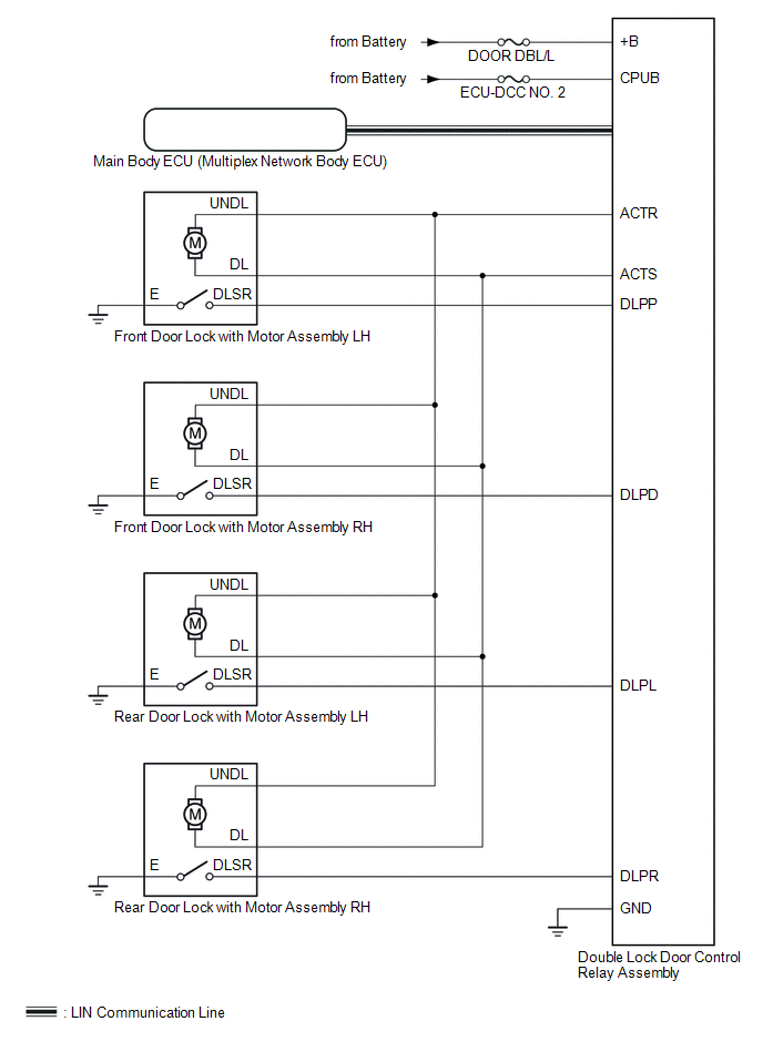
Double Locking System (w/o Toyota Safety Sense P)
 Communication Table
|
Sender |
Receiver |
Signal |
Line |
|---|---|---|---|
|
Double Lock Door Control Relay Assembly |
Main Body ECU (Multiplex Network Body ECU) |
Double lock position switch signal |
LIN |
|
Main Body ECU (Multiplex Network Body ECU) |
Double Lock Door Control Relay Assembly |
Double lock set/unset request Signal |
LIN |
 System Description
SYSTEM DESCRIPTION
POWER DOOR LOCK CONTROL SYSTEM DESCRIPTION
(a) The power door lock system locks/unlocks all doors.
The main body ECU (multiplex network body ECU) receives lock/unlock request sig ...
 How To Proceed With Troubleshooting
CAUTION / NOTICE / HINT
HINT:
Use the following procedure to troubleshoot the power door lock control
system.
*: Use the Techstream.
PROCEDURE
1.
VEHIC ...
Other materials:
Toyota CH-R Service Manual > Meter / Gauge System: Terminals Of Ecu
TERMINALS OF ECU
COMBINATION METER ASSEMBLY
(a) Disconnect the combination meter assembly connectors.
(b) Measure the voltage on the wire harness side connector according to the value(s)
in the table below.
Terminal No.
Wiring Color
Terminal Description
...
Toyota CH-R Service Manual > Can Communication System: Check Bus 1 Lines for Short Circuit
DESCRIPTION
There may be a short circuit between the CAN main bus lines and/or CAN branch
lines when the resistance between terminals 23 (CA1H) and 8 (CA1L) of the central
gateway ECU (network gateway ECU) is below 54 Ω.
Symptom
Trouble Area
Resistance b ...
Toyota C-HR (AX20) 2023-2026 Owner's Manual
Toyota CH-R Owners Manual
- For safety and security
- Instrument cluster
- Operation of each component
- Driving
- Interior features
- Maintenance and care
- When trouble arises
- Vehicle specifications
- For owners
Toyota CH-R Service Manual
- Introduction
- Maintenance
- Audio / Video
- Cellular Communication
- Navigation / Multi Info Display
- Park Assist / Monitoring
- Brake (front)
- Brake (rear)
- Brake Control / Dynamic Control Systems
- Brake System (other)
- Parking Brake
- Axle And Differential
- Drive Shaft / Propeller Shaft
- K114 Cvt
- 3zr-fae Battery / Charging
- Networking
- Power Distribution
- Power Assist Systems
- Steering Column
- Steering Gear / Linkage
- Alignment / Handling Diagnosis
- Front Suspension
- Rear Suspension
- Tire / Wheel
- Tire Pressure Monitoring
- Door / Hatch
- Exterior Panels / Trim
- Horn
- Lighting (ext)
- Mirror (ext)
- Window / Glass
- Wiper / Washer
- Door Lock
- Heating / Air Conditioning
- Interior Panels / Trim
- Lighting (int)
- Meter / Gauge / Display
- Mirror (int)
- Power Outlets (int)
- Pre-collision
- Seat
- Seat Belt
- Supplemental Restraint Systems
- Theft Deterrent / Keyless Entry

0.0068