Toyota CH-R Service Manual: Installation
INSTALLATION
PROCEDURE
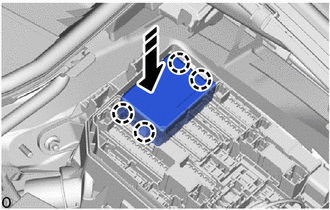
1. INSTALL NO. 1 INTEGRATION RELAY
(a) Connect the 2 connectors.
(b) Engage the claws to install the No. 1 integration relay as shown in the illustration.
.png) |
Install in this Direction |
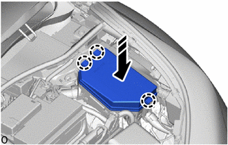
2. INSTALL NO. 1 RELAY BLOCK COVER
(a) Engage the claws to install the No. 1 relay block cover as shown in the illustration.
|
|
Install in this Direction |
3. CONNECT CABLE TO NEGATIVE BATTERY TERMINAL
NOTICE:
When disconnecting the cable, some systems need to be initialized after the cable is reconnected.
Click here
.gif)
 Removal
REMOVAL
CAUTION / NOTICE / HINT
The necessary procedures (adjustment, calibration, initialization, or registration)
that must be performed after parts are removed and installed, or replaced during ...
 Main Body Ecu
...
Other materials:
Toyota CH-R Service Manual > Occupant Classification System: Lost Communication with Multi-axis Acceleration Sensor Module (U0125,U0129)
DESCRIPTION
The occupant detection ECU sends/receives signals to/from each ECU via CAN communication.
DTC No.
Detection Item
DTC Detection Condition
Trouble Area
U0125
Lost Communication with Multi-axis Acceleration Sensor Mod ...
Toyota CH-R Service Manual > Tire Pressure Warning System: Diagnostic Trouble Code Chart
DIAGNOSTIC TROUBLE CODE CHART
Tire Pressure Warning ECU and Receiver
DTC No.
Detection Item
Note
Link
B1247
Tire Pressure Monitor Receiver Communication Stop
This DTC is for main body ECU (multiplex network body ECU ...
Toyota C-HR (AX20) 2023-2026 Owner's Manual
Toyota CH-R Owners Manual
- For safety and security
- Instrument cluster
- Operation of each component
- Driving
- Interior features
- Maintenance and care
- When trouble arises
- Vehicle specifications
- For owners
Toyota CH-R Service Manual
- Introduction
- Maintenance
- Audio / Video
- Cellular Communication
- Navigation / Multi Info Display
- Park Assist / Monitoring
- Brake (front)
- Brake (rear)
- Brake Control / Dynamic Control Systems
- Brake System (other)
- Parking Brake
- Axle And Differential
- Drive Shaft / Propeller Shaft
- K114 Cvt
- 3zr-fae Battery / Charging
- Networking
- Power Distribution
- Power Assist Systems
- Steering Column
- Steering Gear / Linkage
- Alignment / Handling Diagnosis
- Front Suspension
- Rear Suspension
- Tire / Wheel
- Tire Pressure Monitoring
- Door / Hatch
- Exterior Panels / Trim
- Horn
- Lighting (ext)
- Mirror (ext)
- Window / Glass
- Wiper / Washer
- Door Lock
- Heating / Air Conditioning
- Interior Panels / Trim
- Lighting (int)
- Meter / Gauge / Display
- Mirror (int)
- Power Outlets (int)
- Pre-collision
- Seat
- Seat Belt
- Supplemental Restraint Systems
- Theft Deterrent / Keyless Entry

0.0096