Toyota CH-R Service Manual: Removal
REMOVAL
CAUTION / NOTICE / HINT
The necessary procedures (adjustment, calibration, initialization, or registration) that must be performed after parts are removed and installed, or replaced during the No. 1 integration relay removal/installation are shown below.
Necessary Procedure After Parts Removed/Installed/Replaced|
Replaced Part or Performed Procedure |
Necessary Procedure |
Effect/Inoperative Function when Necessary Procedure not Performed |
Link |
|---|---|---|---|
|
Disconnect cable from negative battery terminal |
Initialize back door lock |
Power door lock control system |
|
|
Memorize steering angle neutral point |
Lane departure alert system (w/ Steering Control) |
|
|
|
Pre-collision system |
PROCEDURE
1. PRECAUTION
NOTICE:
After turning the ignition switch off, waiting time may be required before disconnecting the cable from the negative (-) battery terminal. Therefore, make sure to read the disconnecting the cable from the negative (-) battery terminal notices before proceeding with work.
Click here
.gif)
2. DISCONNECT CABLE FROM NEGATIVE BATTERY TERMINAL
Click here
NOTICE:
When disconnecting the cable, some systems need to be initialized after the cable is reconnected.
Click here
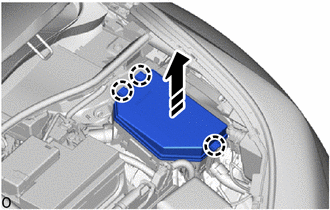
3. REMOVE NO. 1 RELAY BLOCK COVER
(a) Disengage the claws to remove the No. 1 relay block cover as shown in the illustration.
.png) |
Remove in this Direction |
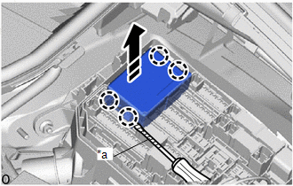
4. REMOVE NO. 1 INTEGRATION RELAY
(a) Using a screwdriver with its tip wrapped in protective tape, disengage the claws.
|
*a |
Protective Tape |
|
|
Remove in this Direction |
(b) Pull up the No. 1 integration relay as shown in the illustration.
NOTICE:
When pulling the No. 1 integration relay, take care not to damage it.
|
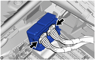
(c) Disconnect the 2 connectors to remove the No. 1 integration relay. NOTICE: When pulling the No. 1 integration relay, take care not to damage it. |
|
 Inspection
INSPECTION
PROCEDURE
1. INSPECT NO. 1 INTEGRATION RELAY
(a) IG1 NO. 3 RELAY:
(1) Measure the resistance according to the value(s) in the table below.
Standard Resistance:
...
 Installation
INSTALLATION
PROCEDURE
1. INSTALL NO. 1 INTEGRATION RELAY
(a) Connect the 2 connectors.
(b) Engage the claws to install the No. 1 integration relay as shown in the illustration.
...
Other materials:
Toyota CH-R Service Manual > Lighting System: Light Sensor Circuit Malfunction (B1244)
DESCRIPTION
The automatic light control sensor detects ambient light. The sensor creates
an electrical signal based on the amount of light detected, and sends the signal
to the main body ECU (multiplex network body ECU). The main body ECU (multiplex
network body ECU) turns on or off the headl ...
Toyota CH-R Service Manual > Rear Center Seat Outer Belt Assembly: Inspection
INSPECTION
PROCEDURE
1. INSPECT REAR CENTER SEAT OUTER BELT ASSEMBLY
(a) Before installing the rear center seat outer belt assembly, check
the ELR function.
NOTICE:
Do not disassemble the retractor.
(1) When the inclination of the retractor is between 0° and 20°, check
...
Toyota C-HR (AX20) 2023-2026 Owner's Manual
Toyota CH-R Owners Manual
- For safety and security
- Instrument cluster
- Operation of each component
- Driving
- Interior features
- Maintenance and care
- When trouble arises
- Vehicle specifications
- For owners
Toyota CH-R Service Manual
- Introduction
- Maintenance
- Audio / Video
- Cellular Communication
- Navigation / Multi Info Display
- Park Assist / Monitoring
- Brake (front)
- Brake (rear)
- Brake Control / Dynamic Control Systems
- Brake System (other)
- Parking Brake
- Axle And Differential
- Drive Shaft / Propeller Shaft
- K114 Cvt
- 3zr-fae Battery / Charging
- Networking
- Power Distribution
- Power Assist Systems
- Steering Column
- Steering Gear / Linkage
- Alignment / Handling Diagnosis
- Front Suspension
- Rear Suspension
- Tire / Wheel
- Tire Pressure Monitoring
- Door / Hatch
- Exterior Panels / Trim
- Horn
- Lighting (ext)
- Mirror (ext)
- Window / Glass
- Wiper / Washer
- Door Lock
- Heating / Air Conditioning
- Interior Panels / Trim
- Lighting (int)
- Meter / Gauge / Display
- Mirror (int)
- Power Outlets (int)
- Pre-collision
- Seat
- Seat Belt
- Supplemental Restraint Systems
- Theft Deterrent / Keyless Entry

0.0092