Toyota CH-R Service Manual: Inspection
INSPECTION
PROCEDURE
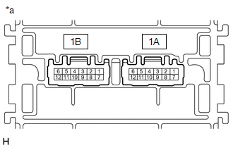
1. INSPECT NO. 1 INTEGRATION RELAY
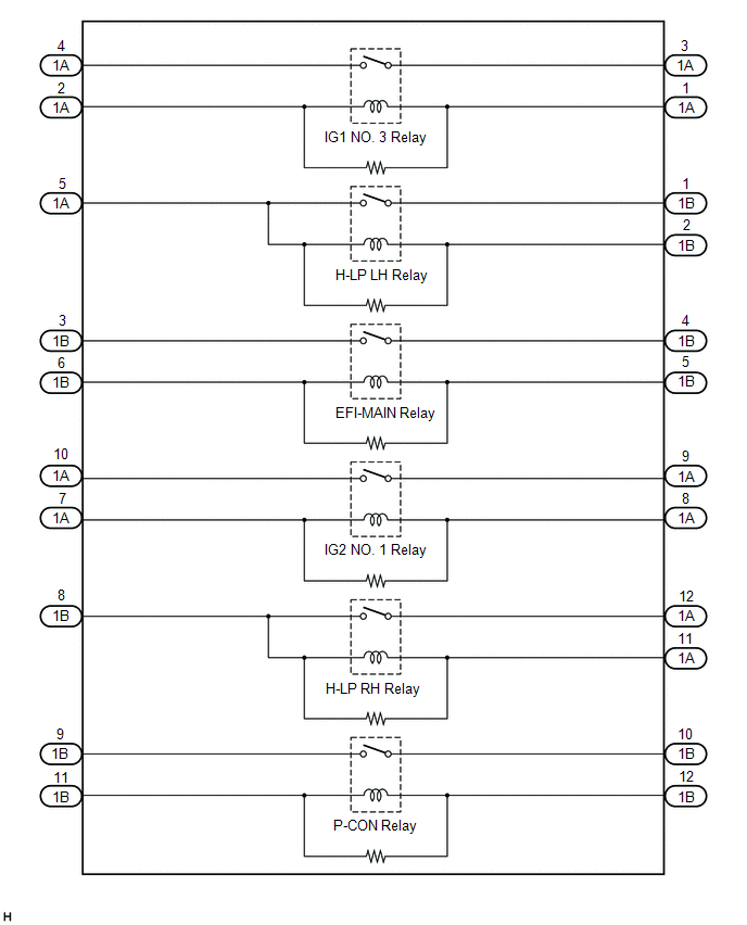
(a) IG1 NO. 3 RELAY:
|
(1) Measure the resistance according to the value(s) in the table below. Standard Resistance:
If the result is not as specified, replace the No. 1 integration relay. |
|
(b) H-LP LH RELAY:
|
(1) Measure the resistance according to the value(s) in the table below. Standard Resistance:
If the result is not as specified, replace the No. 1 integration relay. |
|
(c) EFI-MAIN RELAY:
|
(1) Measure the resistance according to the value(s) in the table below. Standard Resistance:
If the result is not as specified, replace the No. 1 integration relay. |
|
(d) IG2 NO. 1 RELAY:
|
(1) Measure the resistance according to the value(s) in the table below. Standard Resistance:
If the result is not as specified, replace the No. 1 integration relay. |
|
(e) H-LP RH RELAY:
|
(1) Measure the resistance according to the value(s) in the table below. Standard Resistance:
If the result is not as specified, replace the No. 1 integration relay. |
|
(f) P-CON RELAY:
|
(1) Measure the resistance according to the value(s) in the table below. Standard Resistance:
If the result is not as specified, replace the No. 1 integration relay. |
|
 Components
COMPONENTS
ILLUSTRATION
*1
NO. 1 INTEGRATION RELAY
*2
NO. 1 RELAY BLOCK COVER
...
 Removal
REMOVAL
CAUTION / NOTICE / HINT
The necessary procedures (adjustment, calibration, initialization, or registration)
that must be performed after parts are removed and installed, or replaced during ...
Other materials:
Toyota CH-R Service Manual > Smart Key System(for Start Function): Brake Signal Malfunction (B2284)
DESCRIPTION
This DTC is stored when the brake signal sent via direct line and the brake signal
sent via CAN communication do not match.
DTC No.
Detection Item
DTC Detection Condition
Trouble Area
Note
B2284
Brake ...
Toyota CH-R Service Manual > Id Code Box: Removal
REMOVAL
CAUTION / NOTICE / HINT
The necessary procedures (adjustment, calibration, initialization, or registration)
that must be performed after parts are removed, installed, or replaced during the
ID code box (immobiliser code ECU) removal/installation are shown below.
Necessary Procedure Af ...
Toyota C-HR (AX20) 2023-2026 Owner's Manual
Toyota CH-R Owners Manual
- For safety and security
- Instrument cluster
- Operation of each component
- Driving
- Interior features
- Maintenance and care
- When trouble arises
- Vehicle specifications
- For owners
Toyota CH-R Service Manual
- Introduction
- Maintenance
- Audio / Video
- Cellular Communication
- Navigation / Multi Info Display
- Park Assist / Monitoring
- Brake (front)
- Brake (rear)
- Brake Control / Dynamic Control Systems
- Brake System (other)
- Parking Brake
- Axle And Differential
- Drive Shaft / Propeller Shaft
- K114 Cvt
- 3zr-fae Battery / Charging
- Networking
- Power Distribution
- Power Assist Systems
- Steering Column
- Steering Gear / Linkage
- Alignment / Handling Diagnosis
- Front Suspension
- Rear Suspension
- Tire / Wheel
- Tire Pressure Monitoring
- Door / Hatch
- Exterior Panels / Trim
- Horn
- Lighting (ext)
- Mirror (ext)
- Window / Glass
- Wiper / Washer
- Door Lock
- Heating / Air Conditioning
- Interior Panels / Trim
- Lighting (int)
- Meter / Gauge / Display
- Mirror (int)
- Power Outlets (int)
- Pre-collision
- Seat
- Seat Belt
- Supplemental Restraint Systems
- Theft Deterrent / Keyless Entry

0.0072