Toyota CH-R Service Manual: Disassembly
DISASSEMBLY
CAUTION / NOTICE / HINT
NOTICE:
- Do not drop the power steering ECU assembly, strike it with tools or subject it to impacts.
- If the power steering ECU assembly is subjected to an impact, replace it with a new one.
- Do not pull the wire harness.
- Do not allow any moisture to come into contact with the power steering ECU assembly.
- Do not loosen any bolts not mentioned in the procedure.
- Do not allow any foreign matter to contaminate the power steering ECU assembly.
PROCEDURE
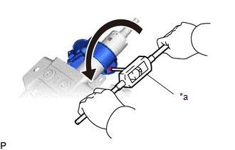
1. REMOVE TRANSPONDER KEY COIL (w/o Smart Key System)
Click here
.gif)
2. REMOVE UPPER STEERING COLUMN BRACKET WITH SWITCH ASSEMBLY (w/o Smart Key System)
(a) Secure the steering column assembly in a vise between aluminum plates.
NOTICE:
Do not overtighten the vise.
(b) Using a center punch, mark the center of the tapered-head bolt.
(c) Using a 3 to 4 mm (0.119 to 0.157 in.) drill, drill a hole in the bolt.
|
(d) Using a screw extractor, remove the bolt and upper steering column bracket with switch assembly from the steering column assembly. |
|
3. REMOVE IGNITION SWITCH LOCK CYLINDER ASSEMBLY (w/o Smart Key System)
|
(a) Turn the ignition switch to ACC. |
|
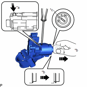
(b) Insert the tip of a screwdriver into the hole in the upper steering column bracket assembly as shown in the illustration, and pull the ignition switch lock cylinder out until its claw comes into contact with the stopper of the upper steering column bracket assembly.
NOTICE:
Pull the ignition switch lock cylinder assembly out until its claw comes into contact with the stopper of the upper steering column bracket assembly. Otherwise, the following procedure cannot be conducted properly.
|
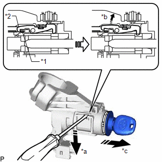
(c) Insert the tip of a screwdriver into the hole in the upper steering column bracket assembly and tilt it downward as shown in the illustration to detach the claw of the ignition switch lock cylinder. Then pull out the ignition switch lock cylinder. |
|
4. REMOVE UN-LOCK WARNING SWITCH ASSEMBLY (w/o Smart Key System)
|
(a) Insert the key. |
|
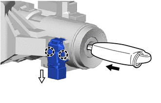
(b) Disengage the 2 claws to remove the un-lock warning switch assembly.
5. REMOVE IGNITION OR STARTER SWITCH ASSEMBLY (w/o Smart Key System)
|
(a) Remove the 2 screws and ignition or starter switch assembly. |
|
6. REMOVE KEY INTERLOCK SOLENOID (w/o Smart Key System)
|
(a) Remove the screw and key interlock solenoid from the upper steering column bracket assembly. |
|
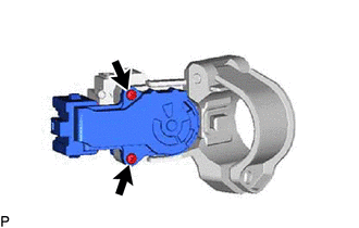
7. REMOVE STEERING LOCK ACTUATOR ASSEMBLY (w/ Smart Key System)
(a) Secure the steering column assembly in a vise between aluminum plates.
NOTICE:
Do not overtighten the vise.
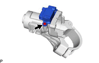
(b) Using a center punch, mark the center of the tapered-head bolt.
(c) Using a 3 to 4 mm (0.119 to 0.157 in.) drill, drill a hole in the bolt.
|
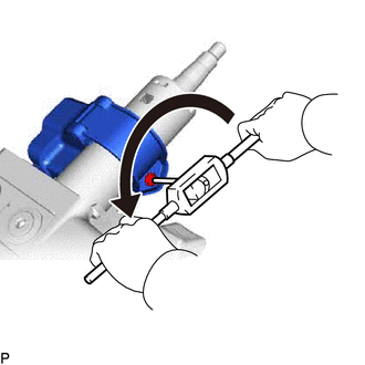
(d) Using a screw extractor, remove the bolt and steering lock actuator assembly from the steering column assembly. |
|
8. REMOVE POWER STEERING ECU ASSEMBLY
Click here
9. REMOVE ELECTRIC POWER STEERING MOTOR SHAFT DAMPER
Click here
 Removal
REMOVAL
CAUTION / NOTICE / HINT
The necessary procedures (adjustment, calibration, initialization, or registration)
that must be performed after parts are removed, installed, or replaced during th ...
 Inspection
INSPECTION
PROCEDURE
1. INSPECT PRELOAD
(a) Secure the steering column assembly in a vise using aluminum plates,
cloths and wooden blocks.
NOTICE:
Do not overtight ...
Other materials:
Toyota CH-R Service Manual > Power Steering System: Precaution
PRECAUTION
IGNITION SWITCH EXPRESSION
HINT:
The type of ignition switch used on this model differs according to the specifications
of the vehicle. The expressions listed in the table below are used in this section.
Expression
Ignition Switch (Position)
Engine S ...
Toyota CH-R Service Manual > Outer Rear View Mirror Glass: Inspection
INSPECTION
PROCEDURE
1. INSPECT OUTER MIRROR LH
(a) Check the resistance.
(1) Measure the resistance according the value(s) in the table below.
Standard Resistance:
Tester Connection
Condition
Specified Condition
...
Toyota C-HR (AX20) 2023-2026 Owner's Manual
Toyota CH-R Owners Manual
- For safety and security
- Instrument cluster
- Operation of each component
- Driving
- Interior features
- Maintenance and care
- When trouble arises
- Vehicle specifications
- For owners
Toyota CH-R Service Manual
- Introduction
- Maintenance
- Audio / Video
- Cellular Communication
- Navigation / Multi Info Display
- Park Assist / Monitoring
- Brake (front)
- Brake (rear)
- Brake Control / Dynamic Control Systems
- Brake System (other)
- Parking Brake
- Axle And Differential
- Drive Shaft / Propeller Shaft
- K114 Cvt
- 3zr-fae Battery / Charging
- Networking
- Power Distribution
- Power Assist Systems
- Steering Column
- Steering Gear / Linkage
- Alignment / Handling Diagnosis
- Front Suspension
- Rear Suspension
- Tire / Wheel
- Tire Pressure Monitoring
- Door / Hatch
- Exterior Panels / Trim
- Horn
- Lighting (ext)
- Mirror (ext)
- Window / Glass
- Wiper / Washer
- Door Lock
- Heating / Air Conditioning
- Interior Panels / Trim
- Lighting (int)
- Meter / Gauge / Display
- Mirror (int)
- Power Outlets (int)
- Pre-collision
- Seat
- Seat Belt
- Supplemental Restraint Systems
- Theft Deterrent / Keyless Entry

0.0088