Toyota CH-R Service Manual: Removal
REMOVAL
CAUTION / NOTICE / HINT
The necessary procedures (adjustment, calibration, initialization, or registration) that must be performed after parts are removed, installed, or replaced during the electric power steering column sub-assembly removal/installation are shown below.
Necessary Procedure After Parts Removed/Installed/Replaced|
Replacement Part or Procedure |
Necessary Procedures |
Effects / Inoperative when not performed |
Link |
|---|---|---|---|
|
Disconnect cable from negative battery terminal |
Initialize back door lock |
Power door lock control system |
|
|
Memorize steering angle neutral point |
Lane departure alert system (w/ Steering Control) |
|
|
|
Pre-collision system |
|||
|
Electric power steering column sub-assembly |
Torque sensor zero point calibration |
|
|
PROCEDURE
1. PRECAUTION
Click here
.gif)
2. ALIGN FRONT WHEELS FACING STRAIGHT AHEAD
3. REMOVE HORN BUTTON ASSEMBLY
Click here
4. REMOVE STEERING WHEEL ASSEMBLY
Click here
5. REMOVE LOWER NO. 1 INSTRUMENT PANEL AIRBAG ASSEMBLY
Click here
6. REMOVE LOWER STEERING COLUMN COVER SUB-ASSEMBLY
NOTICE:
Removing the lower steering column cover sub-assembly in the incorrect order will cause the parts to break.
(a) Release the tilt and telescopic lever and fully extend and lower the steering column assembly.
(b) Lock the tilt and telescopic lever.
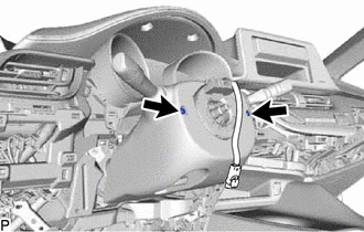
|
(c) Remove the 2 screws. |
|
(d) Push the upper steering column cover and disengage the 4 claws as shown in the illustration.
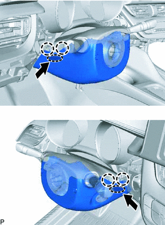
 |
Push Area |
.png) |
Push |
|
(e) Disengage the 2 claws. |
|
(f) Release the tilt and telescopic lever and fully extend and lift the steering column assembly.
(g) Lock the tilt and telescopic lever.
(h) Pull the lower steering column cover sub-assembly toward the rear of the vehicle to disengage the claw and remove the lower steering column cover sub-assembly.
|
|
Place Hand Here |
.png) |
Remove in this Direction |
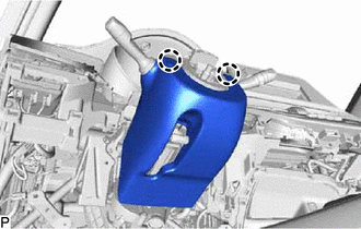
7. REMOVE UPPER STEERING COLUMN COVER
(a) Release the tilt and telescopic lever and fully extend and lower the steering column assembly.
(b) Lock the tilt and telescopic lever.
(c) Disengage the claw and separate the upper steering column cover.
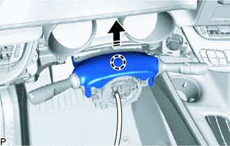
|
|
Remove in this Direction |
|
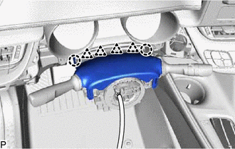
(d) Disengage the 2 claws and 4 clips to remove the upper steering column cover. |
|
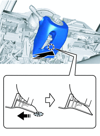
8. REMOVE TURN SIGNAL SWITCH ASSEMBLY WITH SPIRAL CABLE SUB-ASSEMBLY
NOTICE:
- Do not replace the spiral cable with sensor sub-assembly with the battery connected and the ignition switch ON.
- Do not rotate the spiral cable with sensor sub-assembly without the steering wheel assembly installed with the battery connected and the ignition switch ON.
- Ensure that the steering wheel assembly is installed and aligned straight when inspecting the steering sensor.
(a) Disconnect each connector from the turn signal switch assembly with spiral cable sub-assembly.
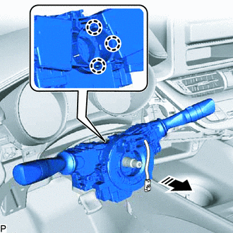
|
|
Remove in this Direction |
(b) Disengage the 3 claws to remove the turn signal switch assembly with spiral cable sub-assembly from the steering column assembly.
9. REMOVE CONSOLE BOX INSERT
Click here
10. REMOVE NO. 1 AIR DUCT
|
(a) Remove the 2 bolts. |
|
(b) Disengage the 3 claws to remove the No. 1 air duct.
11. REMOVE STOP LIGHT SWITCH ASSEMBLY
Click here
12. REMOVE COLUMN HOLE COVER SILENCER SHEET
|
(a) Disengage the claw to open the column hole cover silencer sheet. |
|
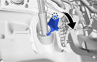
(b) Disengage the 2 claws to remove the column hole cover silencer sheet.
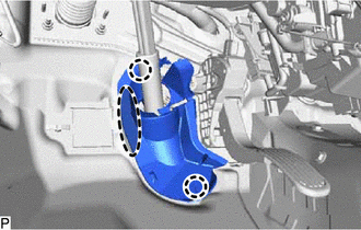
|
|
Place Hand Here |
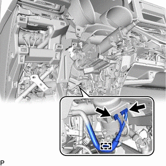
13. SEPARATE NO. 2 STEERING INTERMEDIATE SHAFT ASSEMBLY
|
(a) Put matchmarks on the No. 2 steering intermediate shaft assembly and steering gear assembly. |
|
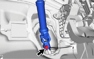
(b) Remove the bolt.
(c) Separate the No. 2 steering intermediate shaft assembly from the steering gear assembly.
14. REMOVE NO. 2 STEERING INTERMEDIATE SHAFT ASSEMBLY
|
(a) Put matchmarks on the No. 2 steering intermediate shaft assembly and steering column assembly. |
|
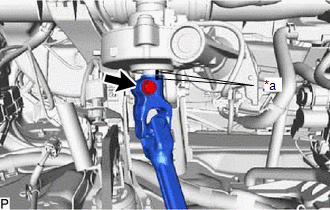
(b) Remove the bolt.
(c) Remove the No. 2 steering intermediate shaft assembly from the steering column assembly.
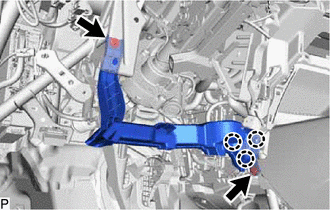
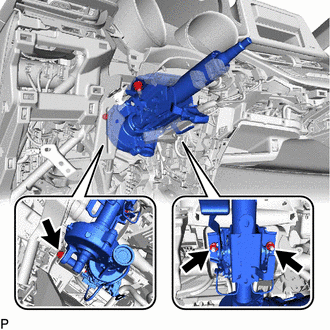
15. REMOVE STEERING COLUMN ASSEMBLY
|
(a) Disconnect the 2 power steering ECU connectors. |
|
(b) Disengage the power steering ECU wire harness clamp.
(c) Disconnect each connector and disengage each clamp from the steering column assembly.
|
(d) Remove the bolt, 2 nuts and steering column assembly. |
|
 Components
COMPONENTS
ILLUSTRATION
*1
STEERING WHEEL ASSEMBLY
-
-
Tightening torque for "Major areas involving basic vehicle perform ...
 Disassembly
DISASSEMBLY
CAUTION / NOTICE / HINT
NOTICE:
Do not drop the power steering ECU assembly, strike it with tools or
subject it to impacts.
If the power steering ECU assembly is subject ...
Other materials:
Toyota CH-R Service Manual > Front Door Outside Moulding: Disassembly
DISASSEMBLY
CAUTION / NOTICE / HINT
HINT:
Use the same procedure for the RH and LH sides.
The procedure listed below is for the LH side.
PROCEDURE
1. REMOVE FRONT DOOR UPPER OUTSIDE MOULDING PAD
(a) Remove the front door upper outside moulding pad.
...
Toyota CH-R Service Manual > Airbag System: Precaution
PRECAUTION
HINT:
In the airbag system, the parts listed below are collectively referred to as
the airbag sensors.
Airbag sensor assembly
Front airbag sensor
Door side airbag sensors
No. 1 side airbag sensor
Floor side airbag sensor
No. 2 side airbag sensor
...
Toyota C-HR (AX20) 2023-2026 Owner's Manual
Toyota CH-R Owners Manual
- For safety and security
- Instrument cluster
- Operation of each component
- Driving
- Interior features
- Maintenance and care
- When trouble arises
- Vehicle specifications
- For owners
Toyota CH-R Service Manual
- Introduction
- Maintenance
- Audio / Video
- Cellular Communication
- Navigation / Multi Info Display
- Park Assist / Monitoring
- Brake (front)
- Brake (rear)
- Brake Control / Dynamic Control Systems
- Brake System (other)
- Parking Brake
- Axle And Differential
- Drive Shaft / Propeller Shaft
- K114 Cvt
- 3zr-fae Battery / Charging
- Networking
- Power Distribution
- Power Assist Systems
- Steering Column
- Steering Gear / Linkage
- Alignment / Handling Diagnosis
- Front Suspension
- Rear Suspension
- Tire / Wheel
- Tire Pressure Monitoring
- Door / Hatch
- Exterior Panels / Trim
- Horn
- Lighting (ext)
- Mirror (ext)
- Window / Glass
- Wiper / Washer
- Door Lock
- Heating / Air Conditioning
- Interior Panels / Trim
- Lighting (int)
- Meter / Gauge / Display
- Mirror (int)
- Power Outlets (int)
- Pre-collision
- Seat
- Seat Belt
- Supplemental Restraint Systems
- Theft Deterrent / Keyless Entry

0.0087