Toyota CH-R Service Manual: Inspection
INSPECTION
PROCEDURE
1. INSPECT FRONT SEAT INNER BELT ASSEMBLY (for Driver Side)
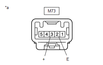
(a) w/o Occupant Classification System:
|
(1) Check the resistance.
Standard Resistance:
If the result is not as specified, replace the front seat inner belt assembly. |
|
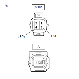
(b) w/ Occupant Classification System:
|
(1) Check the resistance.
Standard Resistance:
If the result is not as specified, replace the front seat inner belt assembly. |
|
2. INSPECT FRONT SEAT INNER BELT ASSEMBLY (for Front Passenger Side)
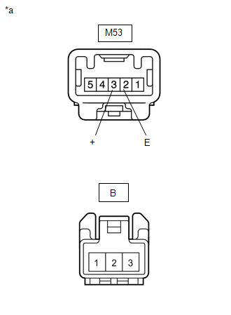
(a) w/o Occupant Classification System:
|
(1) Check the resistance.
Standard Resistance:
If the result is not as specified, replace the front seat inner belt assembly. |
|
 Components
COMPONENTS
ILLUSTRATION
*A
for Driver Side
*B
for Front Passenger Side
*1
FRONT SEAT INNER BELT ASSEMBLY
*2
...
 Removal
REMOVAL
CAUTION / NOTICE / HINT
The necessary procedures (adjustment, calibration, initialization, or registration)
that must be performed after parts are removed and installed, or replaced during ...
Other materials:
Toyota CH-R Service Manual > Shift Lever: Reassembly
REASSEMBLY
PROCEDURE
1. INSTALL SHIFT LEVER HOUSING BRACKET SUB-ASSEMBLY
(a) Engage the 4 claws to install the shift lever housing bracket sub-assembly
to the shift lock control unit assembly.
2. INSTALL SHIFT POSITION INDICATOR
( ...
Toyota CH-R Service Manual > Seat Belt Warning System(w/o Occupant Classification System): Terminals Of Ecu
TERMINALS OF ECU
CHECK MAIN BODY ECU (MULTIPLEX NETWORK BODY ECU) AND INSTRUMENT PANEL JUNCTION
BLOCK ASSEMBLY
*A
Main Body ECU (Multiplex Network Body ECU) with 1 Connector
-
-
*A
Main Body ECU (Multiplex Network Bo ...
Toyota C-HR (AX20) 2023-2026 Owner's Manual
Toyota CH-R Owners Manual
- For safety and security
- Instrument cluster
- Operation of each component
- Driving
- Interior features
- Maintenance and care
- When trouble arises
- Vehicle specifications
- For owners
Toyota CH-R Service Manual
- Introduction
- Maintenance
- Audio / Video
- Cellular Communication
- Navigation / Multi Info Display
- Park Assist / Monitoring
- Brake (front)
- Brake (rear)
- Brake Control / Dynamic Control Systems
- Brake System (other)
- Parking Brake
- Axle And Differential
- Drive Shaft / Propeller Shaft
- K114 Cvt
- 3zr-fae Battery / Charging
- Networking
- Power Distribution
- Power Assist Systems
- Steering Column
- Steering Gear / Linkage
- Alignment / Handling Diagnosis
- Front Suspension
- Rear Suspension
- Tire / Wheel
- Tire Pressure Monitoring
- Door / Hatch
- Exterior Panels / Trim
- Horn
- Lighting (ext)
- Mirror (ext)
- Window / Glass
- Wiper / Washer
- Door Lock
- Heating / Air Conditioning
- Interior Panels / Trim
- Lighting (int)
- Meter / Gauge / Display
- Mirror (int)
- Power Outlets (int)
- Pre-collision
- Seat
- Seat Belt
- Supplemental Restraint Systems
- Theft Deterrent / Keyless Entry

0.0083